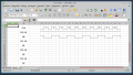
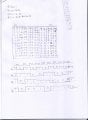
my answer right or wrong?

Thread Starter

full

Joined May 3, 2014
225
It's time for you to step up and give the answers to the questions asked of you.

If you don't understand the questions...say so. You won't get points taken off....because no one is grading you and really want to help you succeed. You have to help us help you. No one is a mind reader.

On edit ...

The attachment shows the initial conditions according to your problem statement. Can you fill in each and every location for the FF's with the appropriate signal level?
thanks ,
I will starting from zero (low) or from one (high) in waveform ?

where is the error in waveform?
 

WBahn

Joined Mar 31, 2012
33,185
thanks ,
I will starting from zero (low) or from one (high) in waveform ?

where is the error in waveform?
You just don't get it, do you?

We are NOT mind readers!

You need to SHOW YOUR WORK!

Do you best to draw a timing diagram that includes the input signals for the flip flops. Even better, show one that has all of the outputs of all the gates. Then, and only then, can we tell where the error is in your waveform.
 

bertus

Joined Apr 5, 2008
23,005
Hello,

As stated: Please include the input signals.
Use the diagram posted by eric to see how the output changes:
(you will only need fig #1 and fig #4).


Joe already gave you a hint how to make the timing diagram:


Please USE the given information and create the timing diagram

Bertus
 
Last edited:

bertus

Joined Apr 5, 2008
23,005
Hello,

Just looking at the thread won't help you.
You will have to make the timing diagram, so we can see what needs correction.

I have made a sheet, where you can edit the boundaries of the cells to show the timing.


I have used LibreOffice to create it.
I have saved the sheet and attached it for you.
(remove the .txt extention, so you can load it into excell or LibreOffice).

If you do not have an office package, you can download LibreOffice here for free:
http://www.libreoffice.org/

Bertus
 

Attachments

Last edited:

WBahn

Joined Mar 31, 2012
33,185
Thank you for FINALLY doing what we've been asking.

You are on the right track, but your answer is assuming that the machine is going down the state table from top to bottom in order. But each row of the table is independent and you could have written them in any order. The final set of columns tells you which state the machine moves into next, right? What does that tell you about which row you need to look at next?
 

Thread Starter

full

Joined May 3, 2014
225
Thank you for FINALLY doing what we've been asking.

You are on the right track, but your answer is assuming that the machine is going down the state table from top to bottom in order. But each row of the table is independent and you could have written them in any order. The final set of columns tells you which state the machine moves into next, right? What does that tell you about which row you need to look at next?
thanks for help me in this question

Congratulations for 8 Thousand communion and help the people
 

Thread Starter

full

Joined May 3, 2014
225
I have question

what different between output zero(Q) and output one(Q)?!
 
Last edited:

bertus

Joined Apr 5, 2008
23,005
Hello,

An initial value of 1 at the outputs will say that the flip-flops all start with high levels at the output Q.

An 0 or L represents a logic low level at the input or output.
An 1 or H represents a logic high level at the input or output.

Bertus
 

absf

Joined Dec 29, 2010
1,968
I have question

what different between output zero(Q) and output one(Q)?!
Are you saying "the difference between the Q output of FF0 and the Q output of FF1" ?

The output of FF0 is a simple /2 circuit with its J and K connected to H. But the J and K of FF1 is controlled by an AND gate with its input from Q of FF0 and !Q of FF3. So it is not the same as FF0.

Allen
 

ericgibbs

Joined Jan 29, 2010
21,568
sorry , I not understand:confused:
hi full,

Dont get discouraged, it can be a little difficult in solving some logic problems.:)

Which word is throwing you off? "initial", "value", "output", or "1"?

Defining:
Initial, is the state of the F/F before any clock pulse, its the starting point.

Value, is either the state of the inputs J,K or the outputs Q or /Q of the F/F.

Output, refers to the state of the F/F outputs Q or /Q.

State, is either High = 1 [True] or Low = 0 [False] , of an Input or Output of the F/F.

So Value and State have the same meaning, High, Low, '1' or '0'

To solve the problem, use a State Table showing the State of each F/F's J,K and Q and /Q [ /Q is one way of writing Bar Q ], for every Clock pulse.

The change in State of this type of F/F will occur on the positive rising edge of the Clock pulse, so you could show the State of each F/F after the Clock pulse has gone Low ie: '0'

E
 
Top