My 555 PWM dosen't work

jpanhalt

Joined Jan 18, 2008
11,087
The house-call is one option.

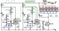
I was thinking along the same lines as Bill. I have usually used a pull-up resistor when modulating one 555 with another. Also, note that his discharge resistor (Rb in the datasheet) is 1K and the charge resistor is up to 470K + 2*1K. That would give a very high duty cycle (T\(_{high}\)= 0.693(Ra+Rb)*C; T\(_{low}\)=0.693Rb*C), which would explain why his voltage measured at pin 3 with a multimeter is effectively the source voltage. A warm transistor would be consistent with that.

John
 

jpanhalt

Joined Jan 18, 2008
11,087
I was fiddling with that sigma function and still couldn't get it to work. That's why my reply was so long in coming.

OK, IC 1 may be working, because as you reduce the pot, the average voltage is decreasing. Now, put a pull-up resistor from Pin3 of IC1 to the supply, VCC (anywhere from 1 to 5.6K).

Actually, that location is close to Litchfield, but probably closer to Wellington. Let's see if we can solve the problem over the mails first.

John
 

Thread Starter

Scott_M

Joined May 8, 2008
37
I attached a 2.2K resistor between pin 3 on IC 1 and power. Now my voltmeter will read output voltage but it will not handle any load . even a small test light will completly kill any voltage reading. With the pot at 100% I read near full voltage, but if I turn it down it stays at full voltage until about 70% then suddenly drops to 6.5 volts and stays there all the way down to 0% on the pot.

By the way I really do appreciate all the help you guys are giving me. !!
 

jpanhalt

Joined Jan 18, 2008
11,087
You don't need much power from IC1. It is sinking the current across the new resistor. Since that is 2.2K, you won't get much current, but you don't need much to trigger IC2.

Where are you reading the output voltage? Still at pin 3, IC1 or pin3 IC2?

I wouldn't worry too much about the actual voltages, because we don't know how fast your meter will respond to the pulses.

With the Freq pot at its lowest, the base frequency from IC1 is about 4.8 KHz (i.e., 1/.693(2Rb+Ra)*C). The duty cycle is greater than 50% (roughly 67%) and only gets greater as the pot is increased.

Ah, it's getting late. I will work more on it tomorrow morning. John
 

Cornelius

Joined Mar 17, 2008
19
I built a similar pwm a while back to play around with hydrogen from water. :D

The one i built was a bit more adjustable than the one you have built, but maybe some ideas there you can use?

The one i built uses the output (pin3) from the first 555 to trigger the second on and off...

But just to control a motor; shouldn't one 555 suffice?
 

Attachments

Wendy

Joined Mar 24, 2008
23,797
OK, I redrew your schematic, minus part designations and some fine detail. I then drew what I was talking about, where I think the problem may be. I used my cookbook sheet, you can find it in PaintCAD on my All About Circuits Blog. Anyhow, I'll work through the numbers tomorrow, but I suspect the problem is the pulse going into the second monostable is too long. This is fixed by conditioning it where only the edge gets through. I got the basics from the 555 datasheet.


jpanhalt

Joined Jan 18, 2008
11,087
I got it to work with one additional component. The problem is in the duty cycle of IC1. It is too short, not too long. Note, there is an inversion from the way were thinking last night. Clear heads help.

Add a diode (1N4148) with the anode connected to the 0.1 uF cap of IC1(pin 2,6) and the cathode (end with the bar) attached to pin 7 of IC1. That is, the diode shorts across the bottom 1K resistor to speed up discharge of the capacitor, thus making a very long duty cycle.

The scope patterns attached show on the bottom trace the output of pin 3 of IC1. The blips down are "off". Notice it is mostly on. The top trace is of the output at pin 3 of IC2. Low power is on left and high power is on the right. Notice the increased duty cycle.

Keep the pull-up resistor as discussed last night.

John
 

Thread Starter

Scott_M

Joined May 8, 2008
37
Good morning gents.
Once again I would like to thank all of you for your help , much of it is over my head but I am trying to grasp the theory. Where I run into trouble is in Eagle board layout. When the signals are "ripped up " It changes every thing, I am asuming it is simplifying the circut for easier routing. It is at this point that I have trouble comparing it to the schematic.
I have also noticed that you guys have 2 diodes in your designs where mine has one. Should IC 1 also have a diode ?
 

jpanhalt

Joined Jan 18, 2008
11,087
BTW. Scott, I would scrap the pot on IC1. Once you get the frequency, there is no need to change it. With the diode I describe, the frequency will be about 1/3 of what it was without it. I measured a little over 1 KHz for the IC1 oscillator.

I assume your first post this morning was before reading mine. In brief, yes there should be 2 diodes. They do very different things. The one on IC1 controls the duty cycle. The one across the motor is for protection against the inductive kick. John
 

Thread Starter

Scott_M

Joined May 8, 2008
37
OK
Now I'm confused. This is what I was talking about with the board layout. On the board
IC1 / pin2 goes to pin 7 to R4 to C2
pin 6 goes to R4 to to the trim pot ( Edit )
 
Last edited:

jpanhalt

Joined Jan 18, 2008
11,087
Scott said:
On the board
IC1 / pin2 goes to pin 7 to R4 to C2
No, the schematic shows IC1 pin 2 going to IC1 pin 6, which is correct. The resistor and diode are between IC1pin7 and IC1pin2-6.

I wired according to the first, B&W schematic that you posted. I actually hadn't even looked at the Eagle schematic until now.

If you had a scope, it would be easy. Since nothing is getting too hot, that's a good sign.

Here's my suggestion, based on the assumption that the Green schematic (Eagle?) is the same as the B&W one.

1) Remove the 470K pot from IC1. Just make a direct connection between the 1K resistor connected to the positive voltage supply and pin7 of IC1. That removes one variable, namely to what resistance the pot is adjusted.

2) Leave/double check that you have a 1K rsistor between pin7 and pins 2-6 (pins 2 and 6 need to be connected to each other).

3) Put a 1N4148 diode between pin 7 and pins2-6. That is , put the diode right across the 1K resistor. The marking (black line) on the diode should be attached to the pin 7 end.

4) If you have an LED, make a test probe with it and a 100 to 200 ohm resistor (100 ohm is best) in series. You can attach that temporarily between pin 3 of IC2 and ground (the cathode end of the LED goes to ground). As you increase the duty cycle, it should glow brighter. You will probably not be able to see it flash, unless the duty cycle is very low and/or you look at it out of the corner of your eye. If you don't have an LED, then your voltmeter should work well enough to show that the average voltage increases as you increase the duty cycle. For this testing, I would leave the motor unconnected.

John
 

Thread Starter

Scott_M

Joined May 8, 2008
37
Thanks again John
To clairify
The photo above is the schematic I drew in eagle and the board layout Eagle generated from it.
The board layout is what I physicaly have.
 

jpanhalt

Joined Jan 18, 2008
11,087
The photo above is the schematic I drew in eagle and the board layout Eagle generated from it.
The board layout is what I physicaly have.
The Eagle schematic looks OK to me and agrees with the B&W schematic. It has some ERC problems (missing junctions), which can create a problem in the schematic capture part of the operation. For example, the junction of the "wire" from pin6 to pin2 on IC1 is clearly intended, but not shown. It needs a "dot" to ensure Eagle knows the wires are joined.

Now, if you did the PCB from the schematic and if Eagle did not think the wires were joined, the PCB will be wrong.

The other missing junction is between pins 6 and 7 on IC2. Again, it is clear (relatively) what you mean, but Eagle may not know it.

In Eagle, with your schmatic showing, click on Tools, then ERC. Highlight the ERC, copy (edit menu), paste to notebook or whatever, and post the result here as a text file. Knowing the ERC may help find the error in the board, if there is one.

John
 

Thread Starter

Scott_M

Joined May 8, 2008
37
I am beginning to think that this may be a lost cause. All these jumpers are cluttering up the board.

So If I were to start over what would you guys suggest ?
Again the ultimate goal is to control a 12V DC motor with a max load of 2 amps. I think a 6 to 12 volt range would be sufficent but will need as much power at the low end as possible. It also needs to start at 6V.
Tranistors I have on hand
TIP31C
TIP3055
TIP120 Darlington

Pots I have on hand

1K, 5K, 10K, 50K, 250K, 1M

Diodes
IN34A
NTE110MP
1N4148
1N4001-4002-4004-4007

John looks like we cross posted again
 

jpanhalt

Joined Jan 18, 2008
11,087
I am beginning to think that this may be a lost cause. All these jumpers are cluttering up the board.
Are there jumpers we haven't discussed? So far, you have the pull-up resistor (which may not be absolutely necessary, but leave it for now), and a diode soldered across a resistor. You can just solder it to the leads of the resistor.

Getting rid of the pot is a jumper, but it is just between the two holes that were left when the pot was removed.

Are there any others?

Scott said:
So If I were to start over what would you guys suggest ?
Again the ultimate goal is to control a 12V DC motor with a max load of 2 amps. I think a 6 to 12 volt range would be sufficient but will need as much power at the low end as possible. It also needs to start at 6V.
Your current circuit probably is salvageable, I think. At least, I think it would be good experience to get it working and to see of the motor behaves the way you want it to. A new circuit could have just as many or more problems.

As advice for the future, regardless of how many times I check a schematic, I always run the ERC. It is not that infrequent that I end up saying, boy what a dumb mistake. Or, why can't Eagle see what I mean?:D One really common problem is when you connect a wire to a symbol, such as a ground, power supply, or resistor, the wire will look like it is connected, but it really isn't from Eagle's standpoint. The wire may just be laying on the symbol. If you click on the symbol and wiggle it, you will see what I mean. Well, that situation (unconnected wires) creates real havoc on the schematic. The component may be there, but the connection isn't.

As for the 6V or 12V question, remember with PWM at low frequency and with a small motor, the motor will be seeing 12V, it will just be turned on and off 1000 times per second. That is different than seeing just 6V for example. Whether the slowest operating speed will be able to break lose and start the motor is another question, which you will have to determine by experiment. As for 6V vs. 12V, I would stay with the 12V as it will result in lower current for the same power.

John
 
Top