My 555 PWM dosen't work

Thread Starter

Scott_M

Joined May 8, 2008
37
Howdy folks
I have been looking around and you have a very nice site here ! Hopefully someone can help me. I am a novice in the world of electronics. Basicaly I know just enough to get myself into trouble. Which I think is what happened here. Long story short , I need to control a small dc motor about 1-2 amps max current. I found several schematics and settled on this one beacuse I had all the parts. ( Link to webpage )


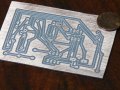
I redrew the schematic and then did a board layout in Eagle and generated some g-code and milled the board on my cnc mill. Somewhere in this process I screwed somthing up. I have looked at everything for two days and can't figure where I went wrong.
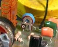
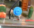
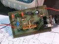
Here are the redrawn schematics and layouts for the board and the finished project. I was really hoping that someone will spot my error/errors. Please don't be afraid to tell it like it is..I have pretty tuff skin


Attachments

Thread Starter

Scott_M

Joined May 8, 2008
37
Just in case... I thought I would add that the IC's have been "mirrored" in the schematic and board layout so the will be correct when finished. As in the IC is on one side of the board and the traces are on the other.
 

Cornelius

Joined Mar 17, 2008
19
Your pots....

They are connected as fixed resistors the way you have connected them. ;)

Try solder a short jumper from one of the sidelegs to the middle leg. :)
 

SgtWookie

Joined Jul 17, 2007
22,230
Cornelius got it ;)

Just a suggestion - you might find it easier to work with your schematics and PCB layout if instead of mirroring everything in the schematic and using the top layer, just use the bottom layer for traces in the board editor, then mirror it when you do your export.

What's your CNC mill? Homebuilt?
 

Wendy

Joined Mar 24, 2008
23,429
It is a very nice job. Definately deserves posting in the projects forum once it's tested out. It looks very professional. As has beem said, a short wire on each pot will fix it, your variable components are currently being used as fixed resistors, the variable pin isn't being used.

What is the ultimate purpose for the project? An as Sarge asked, I'd be interested in how you did it. Don't think I could duplicate it, but I wouldn't mind doing so.
 
Last edited:

Thread Starter

Scott_M

Joined May 8, 2008
37
Thank you for your replies gentleman !! It is appreciated.

The trim pot is a 2 lead 500K and tests 0-510 across the 2 leads. The variable speed pot is a 3 legged one and I had tried it both ways. I just soldered a jumper across the middle pin and one of the outer ones. Still no joy. :confused:

Thank you for the kind words on the project. It looks nice but still does not do anything usefull. ( Kinda like a trophy wife :) )

I have a Tormach PCNC 1100 in MY Shop I also have the 4th axis for it. It is really an awesome machine to have in your basement.

The ultimate project goal is to control a small 12V DC motor that is for a star rolling machine. ( amature pyrotechnician ) I also want to build a 15 amp version for a big DC power supply I have for an anodizing set up.
 

hgmjr

Joined Jan 28, 2005
9,027
That is an interesting device. It appears to have the third terminal internally connected. I would refer to it as a variable resistor just as you have said.

Is the same thing true of your other potentiometer?

hgmjr
 

Thread Starter

Scott_M

Joined May 8, 2008
37
No Sir. The other one is of the three legged variety. And I have tied the middle leg to one of the outers. And it now tests 0-243K over the 2 outside legs.
 

Thread Starter

Scott_M

Joined May 8, 2008
37
Yes. DOA

I have tried probing around on the board with my DVM but I don't know enough about the circuit to know what I am looking for.

Like

With pot set at 100 %
IC 1
pin
1 0V
2 7.2V
3 13.1 V
4 13.1 V
5 9.2 V
6 7.2 V
7 7.2 V
8 13.1 V

IC 2

1 0 V
2 13.1 V
3 13.1 V
4 13.1 V
5 9.3 V
6 15.2 V
7 15.2 V
8 13.1 V

Supply is 13.4 volts
 

hgmjr

Joined Jan 28, 2005
9,027
Your two 555 ic's appear to be mirror imaged. Pin 1 should be in the lower left corner when viewing the device from the top.

hgmjr
 

Thread Starter

Scott_M

Joined May 8, 2008
37
They are mirror imaged. The board and schematic are for machining, Components on one side of the board and traces on the other. As explained in post #2
 

hgmjr

Joined Jan 28, 2005
9,027
I saw the explanation on your earlier post but I did not immediately catch the significance of the comment.

So, the graphic image of the board layout is diliberately shown from the underside of the board. I am more familiar with viewing boards from the top. My bad!

hgmjr
 

beenthere

Joined Apr 20, 2004
15,819
Please don't take this as a criticism - it's always a good idea to work out the basic function on a breadboard before making the PCB. I learned that after cutting a zillion traces and jumping with 30 ga wire.

That CNC mill sure does a pretty job. Hope a jumper or two fixes it.
 

jpanhalt

Joined Jan 18, 2008
11,087
What happens to the measured voltage at Pin3 of the first 555, when the 470K pot is at its minimum?

Is the transistor getting warm?

How far are you from Webster or SR18 and SR301 in Lorain country?

John
 

Wendy

Joined Mar 24, 2008
23,429
Question for the other guys (old hands), doesn't a monostaple 555 require a capacitor and pull up resistor to to trigger properly?
 

hgmjr

Joined Jan 28, 2005
9,027
What happens to the measured voltage at Pin3 of the first 555, when the 470K pot is at its minimum?

Is the transistor getting warm?

How far are you from Webster or SR18 and SR301 in Lorain country?

John
John,

Maybe you can make a house-call to assist Scott_M:)?

hgmjr
 

Thread Starter

Scott_M

Joined May 8, 2008
37
John

I had written down some voltages at about 50% of the 470K pot..

IC 1
pin
1 0V
2 .39V
3 6.1V
4 6.1V
5 4.05V
6 .39V
7 .4V
8 6.1V

IC 2
pin
1 0V
2 6.1
3 0V
4 6.1V
5 4.1V
6 .08V
7 .08V
8 6.1V

No the transistor does not get warm.
I am not sure where Webster is. 301 & 18 is about Litchfield ? I am about 15-20 min from Litchfield.


beenthere

To be honest ... I had trouble on the breadboard too :confused: I was hoping that letting the computer do it would fix everything. ( Yea right ).
 
Top