Mutual inductance in LtSpice

Thread Starter

Michael777

Joined Aug 25, 2014
8
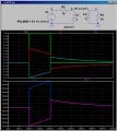
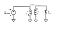
I am new to LtSpice and trying to demonstrate mutual inductance between two circuits.The wires of the two circuits between which the mutual inductance occurs are represented by inductances L1 and L2 in the circuit equivalent as shown.I have considered both wires to be of length 1m, 0.5cm radius each and placed 1cm apart in my calculations. What spice directive can I employ to demonstrate the voltage drop across the load Rl? (PULSE 0 12 0 0.5 0.5 1 2 1), .tran 2? Any corrections and suggestions would be really helpful.
 

Attachments

Thread Starter

Michael777

Joined Aug 25, 2014
8
Thank you for the help. why does the voltage v(b) reduce to -0.2v instaed of 0v at the end of the pulse? Is it because of the self induced emf of the inductor L1?
 

MikeML

Joined Oct 2, 2009
5,444
Thank you for the help. why does the voltage v(b) reduce to -0.2v instaed of 0v at the end of the pulse? Is it because of the self induced emf of the inductor L1?
R2 and L1 are a series RL circuit that have a time constant τ. If the applied voltage pulse were wide enough (several τ), over time the final current would be 100mA (determined only by V1/R1), and the voltage V(b) would be zero.

Now when V1 switches the other way, there is already a current established in L1 so we have to wait longer for the currents to die out...

I choose the pulse width to be only as long as it takes the current in L1 to get to 0.07A, my choice.

Now, let me ask you to explain something. Why does the red trace V(b) step from 0V to 0.5V in the initial step (instead of 0 to 1V)?
 
Last edited:

Thread Starter

Michael777

Joined Aug 25, 2014
8
R2 and L1 are a series RL circuit that have a time constant τ. If the applied voltage pulse were wide enough (several τ), over time the final current would be 100mA (determined only by V1/R1), and the voltage V(b) would be zero.

Now when V1 switches the other way, there is already a current established in L1 so we have to wait longer for the currents to die out...

I choose the pulse width to be only as long as it takes the current in L1 to get to 0.07A, my choice.

Now, let me ask you to explain something. Why does the red trace V(b) step from 0V to 0.5V in the initial step (instead of 0 to 1V)?

Attributing the circuit to be a transformer, the current in the primary circuit would be equal to the source voltage divided by the sum of resistance and the reflected load resistance (I1=Vs/(R2+R1) = 0.05A). The Voltage across L1 would be (Vb= I1*R1, Vb=0.05*10=0.5V) in the initial step. After 100ms the induced emf results in a voltage drop(Vb = Vs*e^(-R1*t/L1) = 0.3V). I'm not sure whether this is the right explanation, please feel free to let me know if i'm wrong.
 

MikeML

Joined Oct 2, 2009
5,444
Attributing the circuit to be a transformer, the current in the primary circuit would be equal to the source voltage divided by the sum of resistance and the reflected load resistance (I1=Vs/(R2+R1) = 0.05A). The Voltage across L1 would be (Vb= I1*R1, Vb=0.05*10=0.5V) in the initial step. After 100ms the induced emf results in a voltage drop(Vb = Vs*e^(-R1*t/L1) = 0.3V). I'm not sure whether this is the right explanation, please feel free to let me know if i'm wrong.
I see that you understand ideal transformers...
 
Top