Facebook
 Google
 GitHub
 Linkedin
Hello everyone,
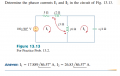
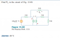
Actually I not understand the Mutual Inductance analysis circuit, but I do one problem ....
Please can you check my solution true or wrong,
thanks,
Actually I not understand the Mutual Inductance analysis circuit, but I do one problem ....
Please can you check my solution true or wrong,
thanks,
Attachments
-
649.9 KB Views: 96