Facebook
 Google
 GitHub
 Linkedin
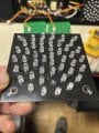
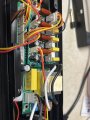
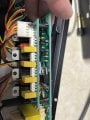
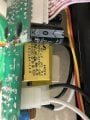
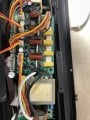
I have an older set of stage lights, from Chauvet, called Stage Bank Pack. 2 fixtures, with 4 LED color panels in each. Each panel has about 45 individual LEDs. One panel does not light at all; another panel has about half not working. I’m getting power to the failed one connector, but can’t find any trace of anything on the board. I’ve reflowed all of the LEDs too. I’ve flexed the panel.
Chauvet company tells me they are obsolete and have nothing on them anymore. And I can’t find any tech stuff on the net. I can swap another panel in its place and it works.
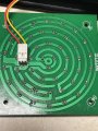
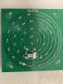
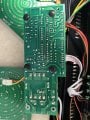
I cannot believe this simple panel is driving me crazy…trying to get some measurements and that seems crazy as well. On DC, the output connector wire shows 146.6v.
I’ll attach a couple of pics.
Any ideas why this panel won’t work?


Chauvet company tells me they are obsolete and have nothing on them anymore. And I can’t find any tech stuff on the net. I can swap another panel in its place and it works.
I cannot believe this simple panel is driving me crazy…trying to get some measurements and that seems crazy as well. On DC, the output connector wire shows 146.6v.
I’ll attach a couple of pics.
Any ideas why this panel won’t work?