
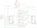
I've been trying to create a 3-channel ultrasonic transceiver (schematic attached), but I'm running into issues with crosstalk between the channels when I transmit. Each 40khz transducer is attached to X1/X2/X3. A transmitter channel is selected on IC2 DG409DJ (TRN_SEL_0, TRN_SEL_1), and the transmitter signal (TRN_SIG_IN) is a 4-pulse 40khz sine wave @ +13/-13V. The receiver channel is selected (RECV_SEL_0, RECV_SEL_1) on IC1 DG409DJ. I've attempted to additionally isolate the signals by using an ADG419 SPDT on each channel, which selectively allows X1/X2/X3 to route towards IC1 or IC2 (transmit or receive).
I tried out the design on a trace-milled PCB, and it does work, but I'm seeing unacceptable crosstalk between the channel that's transmitting and the amplified receiving channel (signal plot attached). The received pulse always contains an attenuated copy of the transmitted pulse. The transducer cables are shielded and moving them around or holding them both in my hands have no effect, and the specs on the DG409+ADG419 should give me something like 75+85dB of isolation, so the only thing I can figure is that the board traces are perhaps coupling?
I am using DIL sockets with DIP8/16 multiplexer ICs inserted into the sockets. Would foregoing the sockets or switching to SMD variants of the ICs significantly reduce the coupling? I've tried to keep the traces as short as possible, but I'm really not very good at board (or circuit!) design. Does anyone have any suggestions about how to better-layout the board? Should I look at different approaches entirely?
Thanks!
Attachments
-
 285.6 KB Views: 20
 -
 499.3 KB Views: 16
 -
 32.4 KB Views: 18


