Facebook
 Google
 GitHub
 Linkedin
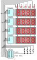
What's the best technique to multiplex a multiplexer?
Say that we have the circuit bellow, but instead of just 4 digits we need 4 rows of 4 digits: what's the best way to do that with a microcontroller, while trying to:
-keep the number of I/O pins used to a minimum
-keep the number of external components to the microcontroller to a minimum
-preferably -though you could if necessary- not using any other ICs.

Thank you in advance for your help.
...
By the way, I saw designs where they don't use the transistors; instead they connect each ground of the displays to their corresponding I/O pin directly, and turn it ON/OFF by changing the mode of the I/O pin from INPUT to OUTPUT.
I tried this technique and it seems to work well -at least with an Arduino- but I was wondering if it has any risks or downside, and if it would also work in other platforms (e.g. with PICs).
Say that we have the circuit bellow, but instead of just 4 digits we need 4 rows of 4 digits: what's the best way to do that with a microcontroller, while trying to:
-keep the number of I/O pins used to a minimum
-keep the number of external components to the microcontroller to a minimum
-preferably -though you could if necessary- not using any other ICs.
Thank you in advance for your help.
...
By the way, I saw designs where they don't use the transistors; instead they connect each ground of the displays to their corresponding I/O pin directly, and turn it ON/OFF by changing the mode of the I/O pin from INPUT to OUTPUT.
I tried this technique and it seems to work well -at least with an Arduino- but I was wondering if it has any risks or downside, and if it would also work in other platforms (e.g. with PICs).