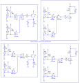
Thanks for the information.Not with a schematic because a JPG file type makes a schematic look very fuzzy. A schematic should be saved as a GIF or PNG file type which makes it look extremely clear.
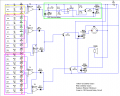
As I pointed out in my previous post, your relay will turn ON when any switch opens, not OFF as you specified. That is, it would if your input circuitry were correct.I would like for some reviews on this schematic, and corrections, and please keep in mind the switches and leds are non moveable. I want the relays to be energized when the switches are closed and if one switch opens the relay does the same, I have a 12v supply with battery back up so power failure is not a problem I posted as a .PNG
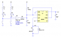
Yeah, considering the symbols I used appear to have unused inputs, I should have mentioned that.Just so it's been covered; you must not leave any INPUTS to a 4000-series CMOS device "floating" (unconnected); they must have a current path to either Vdd (V+) or Vss (GND).
If you leave any inputs floating, you WILL have problems!
Unused OUTPUTS do not have to be connected.
1. As commented by others, your input connections are wrong. The 1K resistor should be connected to +12V instead. You can use my previous circuit or Ron's(better but requires one extra resistor per channel).I would like for some reviews on this schematic, and corrections, and please keep in mind the switches and leds are non moveable. I want the relays to be energized when the switches are closed and if one switch opens the relay does the same, I have a 12v supply with battery back up so power failure is not a problem I posted as a .PNG
This is pretty typical in industry. If there is a failure or break anywhere, the relay's solenoid becomes de-energized, and the contacts to the alarm are made (closed).3. I purposely choose to energise the relay when switch is open to save energy and extend the life of relay. What is your reason of continuously energising the output relays instead of energising them only in alarm state?
What happens when the transistor throws a short circuit? How can it be monitored? Which is more likely, a transistor goes short or a relay become open circuited?This is pretty typical in industry. If there is a failure or break anywhere, the relay's solenoid becomes de-energized, and the contacts to the alarm are made (closed).
If you are driving a PNP, you need an OR gate. You can use diodes to make an OR gate. I already went through that mental exercise. Be aware that diodes have no gain, and they shift the logic levels, so you may have difficulty getting your PNP to turn off.I think I agree after looking at the truth table for a AND gate how can this be done with diodes, if 1n4148 will work have 250 on stock here and it appears so 75V @450ma so I guess next question is how to calcuate the resistor
Re: My AND gate comment, others mentioned this.this is why I ask ron, I am trying to learn, back to what I asked on page 4, any input about the 4071's working for each input, not just the delayed, and what do you recommend for the PNP's? I'm sure the 50v polar caps will work