Facebook
 Google
 GitHub
 Linkedin
Hello, I'm relatively new here and I'd like some help with a compact powered breadboard project I've been working on.
I don't have much in the way of design yet, but my goal is to have a breadboard connected to two power wires (one V+ and one ground), and the two wires to be attached to a circuit capable of switching between a 3V double AAA battery pack, a 9V battery, and a 5V DC power jack. The only condition is that my limited arsenal of parts only gives me access to one ON/ON toggle switch and a handful of ON/OFF toggle switches. I understand that this issue could be resolved with a simple rotary switch, but I would prefer it didn't have to come to that.
I've bounced around the idea of using a bistable multivibrator, but I don't think it would be as seamless with three different power sources.
My current plan of action is to have a single toggle switch to delegate between 3V and 9V, but both are usurped if the DC jack is plugged in. This is the most elegant solution I could come up with and it sounds reasonably doable, but I can't seem to figure it out.
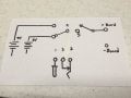
To recap, the circuit needs:
- a toggle switch to control whether the circuit is on or off
- another toggle switch to switch between 3V and 9V
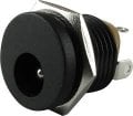
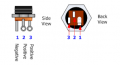
- a DC jack that takes precedence when plugged in
I would appreciate any two cents on how I might go about this or if a setup like this is even possible. Thanks in advance!!!
I don't have much in the way of design yet, but my goal is to have a breadboard connected to two power wires (one V+ and one ground), and the two wires to be attached to a circuit capable of switching between a 3V double AAA battery pack, a 9V battery, and a 5V DC power jack. The only condition is that my limited arsenal of parts only gives me access to one ON/ON toggle switch and a handful of ON/OFF toggle switches. I understand that this issue could be resolved with a simple rotary switch, but I would prefer it didn't have to come to that.
I've bounced around the idea of using a bistable multivibrator, but I don't think it would be as seamless with three different power sources.
My current plan of action is to have a single toggle switch to delegate between 3V and 9V, but both are usurped if the DC jack is plugged in. This is the most elegant solution I could come up with and it sounds reasonably doable, but I can't seem to figure it out.
To recap, the circuit needs:
- a toggle switch to control whether the circuit is on or off
- another toggle switch to switch between 3V and 9V
- a DC jack that takes precedence when plugged in
I would appreciate any two cents on how I might go about this or if a setup like this is even possible. Thanks in advance!!!