Multiple momentary switches to automatic alternate toggle latching outs

Thread Starter

solim888

Joined Apr 11, 2019
1
Does anyone knows if there is any simply solution, or ICs, to do the following:
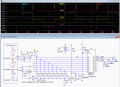
8 momentary switches to control 8 latching outs, only one at the time active.
So, 8 flip flops (seems SR) triggered by momentary push switch to control each own LED at exit, but in the way that one is immediately active after power on (preprogrammed or even better if is possible to remember state before powered off), and when another push switch is pressed to activate another own LED and previous LED to go off. If currently activated line's switch is pressed again, the status should stay unchanged since one line always must be ON.
The IC EDE2208 looks nice as 8 momentary to toggle switches but it doesn't alternate as inputs/outputs are separated from each other. Also it can't start with one out "high", although it can be done with some tricks.
 

sagor

Joined Mar 10, 2019
903
Simplest way to do this, and "remember" last settings is with a small microprocessor like a 20 pin PIC16F series of devices (or 18 pin like a PIC16F628A with internal oscillator)
Those can drive a LED directly, and do de-bouncing of the buttons (if required). On every button press, it can save the current setting in its own EEPROM, and recall that on power up (or you can define a default power up setting)
PortA could be used for the 8 inputs, PortB used for the 8 outputs.
 

MisterBill2

Joined Jan 23, 2018
18,176
The really simple way to achieve all of the required functions would be with an interlocked latching push-button switch bank. pressing any button releases the one previously latched, and because the latch is mechanical it would stay latched even if the power were off. And all the buttons would hold their status until another one was pushed. I have used such arrangements and they worked very well. Of course you would still need to connect the LEDs. But the system would take no programming at all and consume no power at all, except for the LEDs.
 

crutschow

Joined Mar 14, 2008
34,283
You want a "radio push-button" circuit.
Below is one using CD4011 NAND gates as latches, discussed here.
The circuit can be readily expanded to the 8 you want, by adding 5 more stages consisting of the two NAND gates, two resistors and the diode.
The NAND gates come 4 in a package so 8 stages would require 4 CD4011 IC's.

MOSFET M1 resets all the latches to zero at power up. A positive pulse at its gate will also reset all the outputs.

It doesn't remember settings with the power removed but, since it takes only very small leakage current when static, the setting can be maintained by a single 3V lithium coin cell battery OR'd with the power to the IC's using two Schottky diodes, that will last for years.

The LEDs may require a transistor driver, such as a 2N7000, on the CD4011 output, depending upon the LED current and the supply voltage you will use.

The LTspice simulation below shows the operation for various sequences of each switch's momentary operation.
In each case the previous output goes low, and the selected output goes high.
(V1, V2, and V3 are for the simulation only).

 
Last edited:

MisterBill2

Joined Jan 23, 2018
18,176
That circuit shown in post#4 will indeed work as required, but I would suggest using a string of 3 "D" cells for the backup power, along with a supercapacitor. You can use a CD4049 to drive the LEDs if you use it in the current sinking mode. The FETs might possibly be smaller but the 4049 is easier.
 

djsfantasi

Joined Apr 11, 2010
9,156
Simplest way to do this, and "remember" last settings is with a small microprocessor like a 20 pin PIC16F series of devices (or 18 pin like a PIC16F628A with internal oscillator)
Those can drive a LED directly, and do de-bouncing of the buttons (if required). On every button press, it can save the current setting in its own EEPROM, and recall that on power up (or you can define a default power up setting)
PortA could be used for the 8 inputs, PortB used for the 8 outputs.
Simplest, except for crutschow’s solution. Not everyone is microprocessor savvy, and I’d recommend the Arduino platform over the PIC, for a noobie.

An Arduino Nano is a good starting point to learn how to code; even better than the ubiquitous UNO. Later, other platforms will be better sOLUTIOND, once coding skills and chip programming tools are mastered.

But to the TS, for now take a serious look st crutschow’s post. Unless you code in your sleep.
 

MisterBill2

Joined Jan 23, 2018
18,176
The problem with the arduino line is that they choose to use different words for almost everything and so what folks pick up does not transfer to other products so well. And any of those systems take an external computer of some form to program and download the code.
 

djsfantasi

Joined Apr 11, 2010
9,156
The problem with the arduino line is that they choose to use different words for almost everything and so what folks pick up does not transfer to other products so well. And any of those systems take an external computer of some form to program and download the code.
I’ve had this discussion before. It took me 30 seconds to figure out that a sketch is a program and that a shield is an external module.

Supply voltage, ground, analog pin, digital pin, PWM, TTL serial, ( I’m really trying to think of any other terms that are different) are the same in the Arduino environment.

Now explain to me “fuses”? In my 50+ year of programming, for the life of me, I don’t know how a fuse is related to programming. Did my house lights go out?! Arduinos don’t have no stinkin’ fuses.

And you’re telling me that other microprocessors don’t require an external device to load? Obviously, as an introduction to microprocessor technology, I think that having a laptop and a USB cable is much more straightforward than having to purchase some esoteric programming devise. Personally, I think participants on this forum have a laptop or PC, and have no need for a programming device.

Basically, when someone says that Arduinos use some strange language, I hear fear and loathing from someone who’s afraid to learn and unfamiliar with a technology. As I might be when I hear “PIC”, I’ll never be able to program a pic because the only fuses I have are for my car.

My second Arduino project, I implemented a run-time module of a proprietary coding language, with a couple dozen commands, controlling four classes of peripherals. On an Arduino. Over a thousand lined of code. Personally for me at this time, the incremental learning curve is greater than I want. Actually, I feel that with a PIC, I wouldn’t have progressed beyond my first project. What PIC should I have used for my second project? ...with nothing more than a laptop and a USB to microUSB cable.

IMHO
 
Last edited:

AnalogKid

Joined Aug 1, 2013
10,986
Is it just me, or has there been a rash of radio button circuit questions lately.

Here is my entry, from the same question on this forum last June, and other forums more recently. To have the circuit power up with a particular output active, add a 2.2 uF capacitor from that input to GND.

Standard CMOS parts cannot source or sink much current. If you use a 74AC574, the part can source up to 24 mA per output, enough to light a "normal" LED fairly bright.

Hmmm ... I think I'm missing a resistor. I'll post an update tomorrow. What is your operating voltage for your circuit? It affects the switch debounce timing.

ak
SelectorSwitchLatch-4-c.gif
 

MisterBill2

Joined Jan 23, 2018
18,176
I’ve had this discussion before. It took me 30 seconds to figure out that a sketch is a program and that a shield is an external module.

If it took you longer than that to figure out the differences, then it’s on me for underestimating people.

Supply voltage, ground, analog pin, digital pin, PWM, TTL serial, ( I’m really trying to think of any other terms that are different) are the same in the Arduino environment.

Now explain to me “fuses”? In my 50+ year of programming, for the life of me, I don’t know how a fuse is related to programming. Did my house lights go out?! Arduinos don’t have no stinkin’ fuses.

And you’re telling me that other microprocessors don’t require an external device to load? Obviously, as an introduction to microprocessor technology, I think that having a laptop and a USB cable is much more straightforward than having to purchase some esoteric programming devise. Personally, I think participants on this forum have a laptop or PC, and have no need for a programming device.

Basically, when someone says that Arduinos use some strange language, I hear fear and loathing from someone who’s afraid to learn and unfamiliar with a technology. As I might be when I hear “PIC”, I’ll never be able to program a pic because the only fuses I have are for my car.

My second Arduino project, I implemented a run-time module of a proprietary coding language, with a couple dozen commands, controlling four classes of peripherals. On an Arduino. Over a thousand lined of code. Personally for me at this time, the incremental learning curve is greater than I want. Actually, I feel that with a PIC, I wouldn’t have progressed beyond my first project. What PIC should I have used for my second project? ...with nothing more than a laptop and a USB to microUSB cable.

IMHO
The fact is that a lot of folks who post on this forum are quite new to electronics in general and may not have the skills to utilize any sort of processor board. AND the intention of what I have seen in published arduino projects has consistently been to avoid any real technical education of those who build the projects. Perhaps your experience has been different. And what would the motivation be for using entirely different terms for things used elsewhere? And what benefit would be derived from that? In addition, nasty remarks about others are not useful nor beneficial here.

AND, I wonder where anybody mentioned fuses in this entire thread.
 

djsfantasi

Joined Apr 11, 2010
9,156
The fact is that a lot of folks who post on this forum are quite new to electronics in general and may not have the skills to utilize any sort of processor board. AND the intention of what I have seen in published arduino projects has consistently been to avoid any real technical education of those who build the projects. Perhaps your experience has been different. And what would the motivation be for using entirely different terms for things used elsewhere? And what benefit would be derived from that? In addition, nasty remarks about others are not useful nor beneficial here.

AND, I wonder where anybody mentioned fuses in this entire thread.
Excellent points for me to consider. I respect your opinion and apologize for using nasty comments (they’re gone from my original post).

And I’m the person who mentioned fuses. As an example that using different terms is not an Arduino-only “problem”. From the point of view of a noob, I would find that confusing, too.
 

AnalogKid

Joined Aug 1, 2013
10,986
I’m the person who mentioned fuses. As an example that using different terms is not an Arduino-only “problem”. From the point of view of a noob, I would find that confusing,
Not a noob, still confused. In what context have you found "fuse" to be used in a confusing manner? I agree, it took a minute to figure out what a "shield" is, but fuse...?

ak
 

AnalogKid

Joined Aug 1, 2013
10,986
Reworked my old schematic for your application. This is a minimal approach. Expanded versions have more features.

Press any button. After the Rnet-C1 debounce time, the latch is clocked and the output for the pressed button goes high. If it already is high from the last button press, the output stays steady.

The output stage of AC series CMOS can source or sink 24 mA, more than enough to see a standard LED. Since only one output is to be on at a time, you need only one current limiting resistor.

For more output current, add a driver transistor. The 2N7000/7001 gets you around 100-200 mA. For less wiring, a ULN2803/04 gets you 8 drivers of 500 mA each on one package, complete with base resistors and transient protection on the outputs.

ak

EDIT - schematic removed because of DUH. See post #16.
 
Last edited:

crutschow

Joined Mar 14, 2008
34,283
Below is the LTspice simulation of AK's circuit (slightly modified) from post #10 (didn't have his DUH rework ;)).
It's the simplest (fewest parts) discrete radio-pushbutton circuit I've seen, and can be readily expanded by adding more 74HC374/574's.
It shows a 74HC374, which is the same as the 74HC574 except for pinout (I have no idea why there are both configurations :confused:).

It works as expected for the arbitrary sequence of PB presses.
(Only 3 of the 8 input switches are shown).
I have it directly driving LEDs with a nominal ON current of 10mA for a red LED and the series resistor shown.

I don't see a problem with switch-bounce here (everything will switch before the first bounce occurs, and subsequent bounces will have no effect) so I removed capacitor C2 and changed Q2 to a BJT (fewer part types).

I added Q3 and associated parts to provide a power-on reset function that turns all outputs off, since otherwise it could power up with an arbitrary number of LEDs ON and the maximum total 374/574 Vcc current is 50mA.

upload_2019-4-21_13-30-15.png
 

Attachments

AnalogKid

Joined Aug 1, 2013
10,986
OK, I'm back. Here is the reworked reworked version that should actually be correct. It is a bit simpler than Wally's sim, because having the switches switch to GND eliminates his Q2 inverter stage.

Connect the STARTUP capacitor to whichever switch you want to be the power-on default. The cap is the same size as the debounce cap, but it has to charge to a higher voltage before Q1 turns off, so the debounce circuit has time to time out and clock the register.

ak
RadioButtons-8-1.gif
 
Last edited:

crutschow

Joined Mar 14, 2008
34,283
AK, note that the 574 has a minimum clock rise-time

upload_2019-4-21_14-14-0.png
so the R2C1 time constant should be less than that.

But as I stated, I see no reason for a debounce circuit since the IC will change state in a few tens of ns, well before the first bounce, and subsequent bounces will then have no effect on the final output state.
 

AnalogKid

Joined Aug 1, 2013
10,986
AK, note that the 574 has a minimum clock rise-time
I know, but this circuit has *never* has a problem with LS, CMOS, HC, AC, whatever. A very slow clock edge could cause some of the individual latches to latch at different times, different enough to be a problem if the inputs are changing quickly. But in this application they are not, and I don't think it matters how squirrely the latch gets as long as everyone is happy in a few milliseconds.

I get your point about not needing a debounce circuit. For a normal button press of, say, 200 ms, there would be a bounce burst on both pressing ans releasing. Yes, the data line must be high if the clock line is high enough fire the latch, but ... maybe its decades of conditioning, but something about no debouncing doesn't feel right. I'll have to chew on that for a bit.

ak
 

crutschow

Joined Mar 14, 2008
34,283
I know, but this circuit has *never* has a problem with TTL, CMOS, HC, AC, LS, whatever.
You've really tried the actual circuit will all those different logic families?
The Space Shuttle *never* had a problem with ice falling off the top of the shuttle during launch either until --- :eek:.

I just don't like to design outside the devices parameters, even if it's worked many times otherwise.
The spec is there for a reason, and I think it might get "squirrely" by latching into the wrong state.
Otherwise what's the reason for the spec?

I missed the good idea that you could get by with only one common resistor for all the LEDs, saving 7 resistors (below).
It also minimizes the maximum current, even if all outputs come up high at startup, so the power-on reset would not be needed if you don't care how it powers up.

The only possible disadvantage I can see with your circuit in post #16 is that you can't use an N-MOSFET if you need to boost the output current.

upload_2019-4-21_15-46-41.png
 

MisterBill2

Joined Jan 23, 2018
18,176
Wowsers, folks. Yes, running in aeas outside of the intended use can lead into trouble, but I routinely have ignored debounce when there is no chance of a device being triggered back the other way. Look at the input circuit as shown in the much older manuals and see that, at least with CD4xxx series CMOS the input is a gate and so after the first switch on, additional switch-ons have no effect. Just don't exceed the allowablke input voltage.
 
Top