 Facebook
 Google
 GitHub
 Linkedin
Multiple Feedback Filter With Independent Gain not working
Hi,
I'm a hobbyist maker and would like to share this circuit with you.
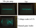
This is a single supply design. An Electret mic is pre-amped then amplified in two more stages using 2 digital pots controlled by a microprocessor. The working signal, called audio, is then filtered into two bandpass signals, their center frequency not greater than 5Khz and a low Q 4-6, using a Multiple Feedback scheme. The filter outputs are gain adjusted in a separate stage producing the final output, biased at Vdd/2, which are sampled and processed by a micro-controller. The output range of the signals to the microprocessor are specified at 0-5v. These signals do not require tight audio performance such as lowest noise because of the manner in which they are processed by the micro-controller. 2 quad amps are used to build the circuit along with the dual digital pot.
The manual gain, determined by the setting of the digital resistor, should be able to range the BP1 and BP2 outputs from near 0v to 5v. Optimally this resistor value should be able to clip the peaks at around 4/5 of it's maximum data value. This pot's digital range has 256 steps. The signal pics shown use a data value of 190 for the manual gain control.
For signal measuring purposes a white noise input is used, frequency set at 1Khz.
I'm having trouble getting the needed gain from the stages following the bandpass filters to satisfy the 0-5v specification. The amplifiers following the BP filters don't seem to be doing their job.
Also the signals, as they develope throught the circuit look 'sloppy'.
The last gain amplifier values are 100k / 10k for a gain of 10.
For BP1 the input looks around 1v pp, the output around 1v pp.
For BP2 the input looks around 0.5v pp, the output around 2v pp.
The signal result of the AGC is specified at around 0.6v pp which the circuit accomplishes with a data value of 230 for it's digital pot having enough headroom to pump up even quieter ambient sound.
The manual gain stage further pumps up the signal to it's desired operating level, in this case using a data value of 190. Plenty of room here with a max of 255.
The BP filter seems working OK.
And then the fail at the BP gain stages which have resistance values for a gain of 10.
The circuit has been put on a 4-layer manufactured board. The board design may be adding to the failure. Until I can verify that the circuit design is working it's useless to scrutinize the board layout and connections.
If anybody finds this circuit interesting and would like to help fix it or improve it, that would be amazing.
Cheers
SparkyS2L
MCP6004
MCP609
MCP42050
Hi,
I'm a hobbyist maker and would like to share this circuit with you.
This is a single supply design. An Electret mic is pre-amped then amplified in two more stages using 2 digital pots controlled by a microprocessor. The working signal, called audio, is then filtered into two bandpass signals, their center frequency not greater than 5Khz and a low Q 4-6, using a Multiple Feedback scheme. The filter outputs are gain adjusted in a separate stage producing the final output, biased at Vdd/2, which are sampled and processed by a micro-controller. The output range of the signals to the microprocessor are specified at 0-5v. These signals do not require tight audio performance such as lowest noise because of the manner in which they are processed by the micro-controller. 2 quad amps are used to build the circuit along with the dual digital pot.
The manual gain, determined by the setting of the digital resistor, should be able to range the BP1 and BP2 outputs from near 0v to 5v. Optimally this resistor value should be able to clip the peaks at around 4/5 of it's maximum data value. This pot's digital range has 256 steps. The signal pics shown use a data value of 190 for the manual gain control.
For signal measuring purposes a white noise input is used, frequency set at 1Khz.
I'm having trouble getting the needed gain from the stages following the bandpass filters to satisfy the 0-5v specification. The amplifiers following the BP filters don't seem to be doing their job.
Also the signals, as they develope throught the circuit look 'sloppy'.
The last gain amplifier values are 100k / 10k for a gain of 10.
For BP1 the input looks around 1v pp, the output around 1v pp.
For BP2 the input looks around 0.5v pp, the output around 2v pp.
The signal result of the AGC is specified at around 0.6v pp which the circuit accomplishes with a data value of 230 for it's digital pot having enough headroom to pump up even quieter ambient sound.
The manual gain stage further pumps up the signal to it's desired operating level, in this case using a data value of 190. Plenty of room here with a max of 255.
The BP filter seems working OK.
And then the fail at the BP gain stages which have resistance values for a gain of 10.
The circuit has been put on a 4-layer manufactured board. The board design may be adding to the failure. Until I can verify that the circuit design is working it's useless to scrutinize the board layout and connections.
If anybody finds this circuit interesting and would like to help fix it or improve it, that would be amazing.
Cheers
SparkyS2L
MCP6004
MCP609
MCP42050
Attachments
-
25.1 KB Views: 10
-
 241.3 KB Views: 4
 -
 324 KB Views: 4


