Facebook
 Google
 GitHub
 Linkedin

I'm trying to design a RF receiver to pick up AM 60khz and what I'm thinking is to make a two-stage BJT amplifiers and an active opamp filter.
For the active op-amp filter I'm trying to use a multiple feedback bandpass filter with middle frequency of 60khz, middle band gain of 1 and bandwidth of 5khz.
To solve for the component values I'm using matlab:
Results:
Which produces the expected Bode plot with the following matlab code:
Using these results I am simulating the circuit using LTSpice:
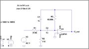
Netlist:
Which produces a frequency response centered at 40kHz (not 60kHz):
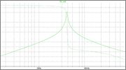
I understand that the matlab and SPICE wont match usually because one is ideal while the other is not. My question is why is their such a discrepitancy between the designed middle frequency of 60khz and the simulated middle frequency of 40khz. How can I modify and/or model my circuit to work for 60khz?
For the active op-amp filter I'm trying to use a multiple feedback bandpass filter with middle frequency of 60khz, middle band gain of 1 and bandwidth of 5khz.
To solve for the component values I'm using matlab:
Rich (BB code):
%Multi-Feedback BandPass OpAmp Filter
syms R1 R2 R3
C1 = 1e-9;
w_m = (1/(C1^2*R3) * (1/R1+1/R2))^0.5;
A_m = R3/(2*R1);
B = 1/(pi*C1*R3);
% Q = 0.5*(1+R1/R2)^0.5*(R3/R1)^0.5;

solu = solve(w_m == 2*pi*60e3, A_m == 1, B == 5e3);

sol_R1 = double(solu.R1);
sol_R2 = double(solu.R2);
sol_R3 = double(solu.R3);

fprintf('\nC1 = %.3e\nR1 = %.3e\nR2 = %.3e\nR3 = %.3e\n\n', C1, sol_R1, sol_R2, sol_R3)
Rich (BB code):
C1 = 1.000e-09
R1 = 3.183e+04
R2 = 1.109e+02
R3 = 6.366e+04
Rich (BB code):
R1 = sol_R1;
R2 = sol_R2;
R3 = sol_R3;
C1 = 1e-9;

num = [1/(R1*C1), 0];
den = [1,...
        2/(R3*C1),...
        1/(C1^2*R3)*(1/R1+1/R2)];

h = tf(num, den);
bode(h);Netlist:
Rich (BB code):
XU1 0 N003 pos neg V_out LM741
V1 pos 0 9
V2 0 neg 9
V3 N001 0 AC 1
R1 N002 N001 31.8k
C2 N003 N002 1n
C1 N002 V_out 1n
R3 N003 V_out 63.66k
R2 N002 0 110
.lib lm741.sub
;tran 0 10m 0 .01
.ac oct 1000 1k 1MEG
.backanno
.endI understand that the matlab and SPICE wont match usually because one is ideal while the other is not. My question is why is their such a discrepitancy between the designed middle frequency of 60khz and the simulated middle frequency of 40khz. How can I modify and/or model my circuit to work for 60khz?