 Facebook
 Google
 GitHub
 Linkedin
Hi,
At the bottom of section 5.0 here it says:
It is not uncommon to see a single reference transistor (Q3 in Figure 7b) controlling two or more current sources (which may be supplying different currents). The reference should always control the current source transistor that has the most stable current. For example, if there were a current source for the input stage and the Class-A amplifier, the reference should always be taken from the source used for the input stage. This minimises any possible cross-coupling between the two current sources.
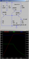
So if you need 2 current sources, instead of using 2 transistors for each, you might save 1 transistor by using the same reference. But I'm not what that circuit would look like. Is the attached circuit what the article is referring to? Q1 and Q2 form the normal current source and Q3 would be the additional current source.
It looks like it works but current source Q3 is not nearly as good as Q2. Searching the net I found multiple current mirrors from the same reference but they all produce the same current (no?) so that can't be it. I would expect the performance of Q3 to be similar if you would swap Q1 for 2 diodes, so while this scheme maybe good enough for some applications, it will be inferior to separate current sources(?).
At the bottom of section 5.0 here it says:
It is not uncommon to see a single reference transistor (Q3 in Figure 7b) controlling two or more current sources (which may be supplying different currents). The reference should always control the current source transistor that has the most stable current. For example, if there were a current source for the input stage and the Class-A amplifier, the reference should always be taken from the source used for the input stage. This minimises any possible cross-coupling between the two current sources.
So if you need 2 current sources, instead of using 2 transistors for each, you might save 1 transistor by using the same reference. But I'm not what that circuit would look like. Is the attached circuit what the article is referring to? Q1 and Q2 form the normal current source and Q3 would be the additional current source.
It looks like it works but current source Q3 is not nearly as good as Q2. Searching the net I found multiple current mirrors from the same reference but they all produce the same current (no?) so that can't be it. I would expect the performance of Q3 to be similar if you would swap Q1 for 2 diodes, so while this scheme maybe good enough for some applications, it will be inferior to separate current sources(?).
Attachments
-
 23.9 KB Views: 40
")


