Multi-stage BJT Amplifiers Input Resistance

Thread Starter

h_ngm_n

Joined Aug 16, 2014
3
Hi all,

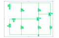
I am working on analyzing a common emitter amp feeding into an emitter follower, and there is one point I am stuck on. Is the input resistance effectively the input resistance of stage 1 only (i.e. the common emitter only) or do I need to take into account the parameters of the second stage as well? I understand the input resistance of the CE amp to be R1||R2||hie.

Any help greatly appreciated, thanks.
 
Last edited:

Thread Starter

h_ngm_n

Joined Aug 16, 2014
3
No, you don't need to take into account the second stage.
The second stage will almost have no effect on Rin of the first stage.
Ok thank you I suspected this but have a few confusing examples in my study materials so just wanted to make sure
 

to3metalcan

Joined Jul 20, 2014
260
There are definitely situations where the second stage can change the impedance of the first, through bootstrapping or negative feedback. But not here! :) Just R1 || R2 || β x R4
 

anhnha

Joined Apr 19, 2012
905
There are definitely situations where the second stage can change the impedance of the first, through bootstrapping or negative feedback. But not here! :) Just R1 || R2 || β x R4
Is the exact value of input resistance of the common emitter R1 || R2 || (β*re + (β +1)R4) ?
 

The Electrician

Joined Oct 9, 2007
2,970
Is the exact value of input resistance of the common emitter R1 || R2 || (β*re + (β +1)R4) ?
It's R1 || R2 || ((β+1)re + (β+1)R4)

And, even without feedback through external components, the transistor's hre parameter, if not zero, will cause the input resistance to be affected by the second stage.
 

anhnha

Joined Apr 19, 2012
905
It's R1 || R2 || ((β+1)re + (β+1)R4)

And, even without feedback through external components, the transistor's hre parameter, if not zero, will cause the input resistance to be affected by the second stage.
I am wondering why it is (β+1)re. According to this model, shouldn't it be β*re?


Attachments

I think I am right.
The input resistance of only BJT with R4 at emitter is β*re + (β +1)R4.
If there is no R4, then the input resistance is either β*re or (β+1)*re. If β is zero, then in the first case the input resistance would be zero, and this is clearly not correct. The (+1) part is there because the emitter current is the sum of the base current and the collector current, and is not just equal to the collector current..
 

anhnha

Joined Apr 19, 2012
905
If there is no R4, then the input resistance is either β*re or (β+1)*re.
I can't figure out why it can be (β+1)*re.
The (+1) part is there because the emitter current is the sum of the base current and the collector current, and is not just equal to the collector current..
Are you talking about β + 1 in (β+1)*R4?
I am confused about this?
It's R1 || R2 || ((β+1)re + (β+1)R4)
 

Jony130

Joined Feb 17, 2009
5,488
Well

re = vbe/ie = Vt/Ie

So vbe = ib*r_pi = ie*re

thus

r_pi =vbe/ib = (Ie/Ib)*re = (β + 1)*re

and

Ie = Ib + Ic = Ib + β*Ib = (β + 1)*ib

so Ie/Ib =
(β + 1)
 

to3metalcan

Joined Jul 20, 2014
260
It's β+1 in both terms because you input a small current (Ib) and the transistor adds a larger collector current (Ib x β). Both of these flow through the emitter together, so the total current is Ie = Ib + (Ib x β) = Ib x (β + 1).

But base current and re are not relevant in most CE analysis because β is hugely more than one and is also not predictable for a given device...variations in β are going to render the other two numbers mostly irrelevant. re becomes more important if R4 is small or zero ohms.
 

MrAl

Joined Jun 17, 2014
11,474
Hi,

Example:
Re=1 ohms (sum of re and RE, re internal, RE external)
Ib=1 amps
1amps*1ohm=1v (voltage drop across Re due to base current alone)
10amps*1ohm=10v (volage drop across Re due to Beta=10 times base current)
Total Re voltage drop=11v
11v/1a=11 ohms input resistance Rin
Rin=(Beta+1)*Re=(10+1)*1 ohm=11 ohms input resistance

A single common emitter stage has Rin dependence on Ic because re is dependent on Ic:
Rin=(Beta+1)*Re=(Beta+1)*(re+RE)=(Beta+1)*(re(Ic)+RE)
which shows the dependence of re on Ic by re(Ic).
Note this shows that even without a second stage the input resistance will be dependent partly on the load resistance because that changes Ic (RL shunts some current to ground or increases current from the power supply source).

It should be noted however that this dependence will be minimal with well chosen RE where RE swamps re, but with purposefully added feedback it will usually change Rin by a much greater factor. Thus it can be said that a stage with added feedback will change Rin more than without added feedback.
 

Veracohr

Joined Jan 3, 2011
772
Ok thank you I suspected this but have a few confusing examples in my study materials so just wanted to make sure
Think about it analytically:

You know how to calculate the input resistance of the CE amp, you know that the output of the CE amp is the collector, and you'll notice there's nothing in the input resistance formula about the collector.

On the other hand, if you swapped the two stages, so that the emitter follower was first and the CE amp second, the input resistance of the second stage would factor in. In that case, the input resistance of the first stage (emitter follower) is determined (in part) by the resistance connected to the emitter, which now includes the input resistance of the second stage.
 

MrAl

Joined Jun 17, 2014
11,474
Think about it analytically:

You know how to calculate the input resistance of the CE amp, you know that the output of the CE amp is the collector, and you'll notice there's nothing in the input resistance formula about the collector.

On the other hand, if you swapped the two stages, so that the emitter follower was first and the CE amp second, the input resistance of the second stage would factor in. In that case, the input resistance of the first stage (emitter follower) is determined (in part) by the resistance connected to the emitter, which now includes the input resistance of the second stage.
Hi,

You must have not read the posts before yours or you would have seen that the input resistance depends partly on the collector current Ic. In most cases this can be minimized with proper selection of RE the external emitter resistance, but it is worth studying the reverse effect anyway.
 
Top