 Facebook
 Google
 GitHub
 Linkedin
Hi All,
I've been working on motor timers for a small Free Flight model aeroplanes (ie not radio controlled) for a local competition and would appreciate some guidance please. I've been learning my way through this project but am very much a hobbyist and would appreciate having any pitfalls pointed out. This thread details the motor timer I've mentioned before in a thread about the other half of the project - the 'Dethermalizer' function that prevents the model from flying away if it catches big thermal lift in the gliding phase: https://forum.allaboutcircuits.com/threads/mic1555-sequential-timer-triggers-on-power-up.182657/ As mentioned before the footprint and weight of the timer needs to be kept to an absolute minimum wherever possible.
In the climb phase the model uses a one cell Lipo at 3.7V running a DC coreless 8mm 'Pager style' motor. The motor is started by a momentary push button and runs for maximum of 8 seconds as a one shot before stopping. The model then glides for as long as possible. The motor timer has gone through a few stages of development as I will outline:
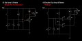
1) The simplest iteration of the timer is one we have used for some years in our model club, a simple resistor/capacitor and MOSFET as shown in the first circuit attachment. However as the rc voltage drops through the linear region of the FET there is a period of decaying motor power and some loss of climbing time.
2) An improved version was to use an LM321 Op Amp Comparator to provide a 'hard stop' by driving the FET gate low when the r/c reaches a reference voltage. However a further problem was that while gliding the coreless motors will freewheel in the airstream which creates a lot of drag and spoils the performance so some sort of propeller brake was required.
3) I had the idea of using a P channel FET to open a short across the motor once it had stopped, but hopefully avoiding any shorting of the battery. I had experimented with the simple timer by matching the gate thresholds of the two FETs so that they did not overlap and avoided shorting the battery. This worked to some degree but wasn't very repeatable. Once the hard stop OP Amp timer came along I initially used the same Op Amp output to drive both the N channel motor FET and the P channel braking FET. This worked in practice, as can be seen here:
With the hard stop, the gate thresholds didn't seem to matter but someone pointed out that even with fast switching there is potential for a brief short. I don't have equipment to detect a short in any case so my first question is: Would driving both FETs on one pin really be problematic or is the switching (both on and off) fast enough to avoid any practical battery short issues? Weight and footprint is everything so if the potential issues are trivial then the simpler circuit would be preferable.
4) In order to solve the 'two FETs on a single output' problem I came up with a double Op Amp version which used a three part voltage divider and a single r/c. This - in theory - was to separate the switching of the motor and the braking short by a few micro seconds. I need it to be as soon as possible to use the back EMF to stop the propeller - if the brake is applied too late the prop continues to spin and will re-gain momentum from the airflow. The resistors in the voltage divider are 470K/3.3K/220K ie with 3.3K separating the ON and Brake. This gives me a ratio 68%/0.47%/32% so I think the braking short is applying about 50 milliseconds after the motor is stopped.
My second question is: Have I solved the problem with this double OP Amp circuit or am I missing something that could still cause issues? I can't really measure the voltage accurately enough (multimeter) to be sure that the Op Amps are working as I hope they are. Will the OP Amps reliably switch in sequence as the r/c voltage falls or is there any source of inaccuracy here that I'm not aware of?
Thanks in a advance for any help and as always I'm open to hearing ideas about how I could achieve a hard motor stop and brake circuit in a simpler, lighter or a smaller footprint.
Thanks,
Jon
I've been working on motor timers for a small Free Flight model aeroplanes (ie not radio controlled) for a local competition and would appreciate some guidance please. I've been learning my way through this project but am very much a hobbyist and would appreciate having any pitfalls pointed out. This thread details the motor timer I've mentioned before in a thread about the other half of the project - the 'Dethermalizer' function that prevents the model from flying away if it catches big thermal lift in the gliding phase: https://forum.allaboutcircuits.com/threads/mic1555-sequential-timer-triggers-on-power-up.182657/ As mentioned before the footprint and weight of the timer needs to be kept to an absolute minimum wherever possible.
In the climb phase the model uses a one cell Lipo at 3.7V running a DC coreless 8mm 'Pager style' motor. The motor is started by a momentary push button and runs for maximum of 8 seconds as a one shot before stopping. The model then glides for as long as possible. The motor timer has gone through a few stages of development as I will outline:
1) The simplest iteration of the timer is one we have used for some years in our model club, a simple resistor/capacitor and MOSFET as shown in the first circuit attachment. However as the rc voltage drops through the linear region of the FET there is a period of decaying motor power and some loss of climbing time.
2) An improved version was to use an LM321 Op Amp Comparator to provide a 'hard stop' by driving the FET gate low when the r/c reaches a reference voltage. However a further problem was that while gliding the coreless motors will freewheel in the airstream which creates a lot of drag and spoils the performance so some sort of propeller brake was required.
3) I had the idea of using a P channel FET to open a short across the motor once it had stopped, but hopefully avoiding any shorting of the battery. I had experimented with the simple timer by matching the gate thresholds of the two FETs so that they did not overlap and avoided shorting the battery. This worked to some degree but wasn't very repeatable. Once the hard stop OP Amp timer came along I initially used the same Op Amp output to drive both the N channel motor FET and the P channel braking FET. This worked in practice, as can be seen here:
With the hard stop, the gate thresholds didn't seem to matter but someone pointed out that even with fast switching there is potential for a brief short. I don't have equipment to detect a short in any case so my first question is: Would driving both FETs on one pin really be problematic or is the switching (both on and off) fast enough to avoid any practical battery short issues? Weight and footprint is everything so if the potential issues are trivial then the simpler circuit would be preferable.
4) In order to solve the 'two FETs on a single output' problem I came up with a double Op Amp version which used a three part voltage divider and a single r/c. This - in theory - was to separate the switching of the motor and the braking short by a few micro seconds. I need it to be as soon as possible to use the back EMF to stop the propeller - if the brake is applied too late the prop continues to spin and will re-gain momentum from the airflow. The resistors in the voltage divider are 470K/3.3K/220K ie with 3.3K separating the ON and Brake. This gives me a ratio 68%/0.47%/32% so I think the braking short is applying about 50 milliseconds after the motor is stopped.
My second question is: Have I solved the problem with this double OP Amp circuit or am I missing something that could still cause issues? I can't really measure the voltage accurately enough (multimeter) to be sure that the Op Amps are working as I hope they are. Will the OP Amps reliably switch in sequence as the r/c voltage falls or is there any source of inaccuracy here that I'm not aware of?
Thanks in a advance for any help and as always I'm open to hearing ideas about how I could achieve a hard motor stop and brake circuit in a simpler, lighter or a smaller footprint.
Thanks,
Jon
Attachments
-
 56.2 KB Views: 14
 -
 74.1 KB Views: 11
Last edited:


