Facebook
 Google
 GitHub
 Linkedin
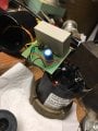
I have a very small motor - it's a recirculating pump that is 1/150hp. It has ceased to run and only hums when energized. The motor is all sealed up - the mechanism by which the motor drives the impeller is via magnets (i.e., the motor appears to turn a magnet inside a sealed metal housing and a similarly equipped impeller that sits on a fixed spindle has a magnetic base.) So, the motor inside is clearly not turning. There is no way to start the motor (turning the impeller assembly by hand does not result in the motor starting up).
It has a motor run capacitor, rated at 3.5 mfd +/- 10% at 280VAC. I have tested it with a capacitance meter and it is returning a capacitance value of 2.77 mfd. That is outside the accepted range, but not significantly so (the range should be 3.15-3.85). Otherwise, the capacitor appears undamaged. There is a single capacitor in the motor, with 2 leads.
The capacitor specs are available here (it is a KNM1228): Motor Running & Motor Starting Capacitors KNM
According to this thread, a difference of an additional 10% wouldn't be expected to cause the observed failure, at least in a larger motor. Elsewhere, I read that an undersized run capacitor would likely cause the motor to never get up to full speed (vs. not starting at all, which is the current problem).
My questions:
1. Given that this is such a small motor, is there a reasonable chance that this small difference (0.38 mfd) would cause the failure of the motor to run? I.e., should I purchase a replacement and try it or is that a waste of time?
2. Is there a way to test the function of the capacitor? I.e., if the capacitance meter returns a value of 2.77 mfd, does that "prove" that the capacitor is functioning? As an analogy, an expired alkaline battery may return an acceptable voltage value but any current draw on the battery would quickly indicate that it had expired - is there a similar situation w/ capacitors?
3. Other thoughts on troubleshooting a completely sealed motor? I have no wiring diagram and there are 5 wires to the motor from the circuit board.