Facebook
 Google
 GitHub
 Linkedin
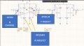
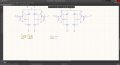
Hi,this is my first time using a mosfet based motor driver. I have this motor driver design set up on a breadboard for a bipolar stepper motor. I was able to drive the motor forwards and backwards for about 5 minutes. I realized that two of the P mosfets were getting hot until they became untouchable. Then I turned off the power supply which was I limited to 6V, 0.8A. Then I turned off the power supply until the mosfets were cold. I turned the supply on again but I didn't send any commands (0000) to the motor driver and I realized that the same mosfets were getting hot again. I tried to move the motor forwards or backwards but it would only stall. I would appreciate if someone could help me troubleshoot the design of the motor driver. The mosfets I am using are 2N7000( 200 mA, 60 VOLTS, RDS(on) = 5 ohms), IRZ44N (VDSS = 55V, RDS(on) = 0.022ΩID = 47A) and 4P03L04 (VDS-30V, RDS(on) 4.1mΩ, ID-80A)
The motor I am using is this one https://www.amazon.com/gp/product/B00PNEQKC0/ref=ppx_yo_dt_b_asin_title_o00_s00?ie=UTF8&psc=1 Nema 17 Rated current 2.0A & resistance 1.4ohm
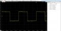
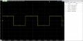
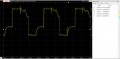
My vcc comes from a dc power supply, I limited the voltage to 6V and the current to 0.8A. My driver levels are these: to stop 0000, for forwards 0101, 0110, 1010, 1001. where the most left bit is CON4 and the most Right bit is CON0. for backwards, 1001, 1010,0110, 0101. I am driving the motor at a range of 50Hz to 200Hz. CON 1 connects to coil A CON 2 connects to coil A' CON 3 connects to coil B and CON 4 connects to coild B'. Additionally the GPIO logic level is 3.3V and the max current output of my MCU is 8mA. I measured the voltage at the drain of the 2n7000 and I was able to see only 2.5-2.7V instead of 3.3V. I'm guessing there must be something wrong with the design since two of the mosfets get hot even when the motor is stopped ( the power supplies shows 0.0008A). When is the motor is on (CCW or CW) the power supply shows 0.35A. When there is a load it rises up to 0.75A
I'll appreciate any suggestions, also I am not suppose to use motor driver ics since it's for a school project.
The motor I am using is this one https://www.amazon.com/gp/product/B00PNEQKC0/ref=ppx_yo_dt_b_asin_title_o00_s00?ie=UTF8&psc=1 Nema 17 Rated current 2.0A & resistance 1.4ohm
My vcc comes from a dc power supply, I limited the voltage to 6V and the current to 0.8A. My driver levels are these: to stop 0000, for forwards 0101, 0110, 1010, 1001. where the most left bit is CON4 and the most Right bit is CON0. for backwards, 1001, 1010,0110, 0101. I am driving the motor at a range of 50Hz to 200Hz. CON 1 connects to coil A CON 2 connects to coil A' CON 3 connects to coil B and CON 4 connects to coild B'. Additionally the GPIO logic level is 3.3V and the max current output of my MCU is 8mA. I measured the voltage at the drain of the 2n7000 and I was able to see only 2.5-2.7V instead of 3.3V. I'm guessing there must be something wrong with the design since two of the mosfets get hot even when the motor is stopped ( the power supplies shows 0.0008A). When is the motor is on (CCW or CW) the power supply shows 0.35A. When there is a load it rises up to 0.75A
I'll appreciate any suggestions, also I am not suppose to use motor driver ics since it's for a school project.
Attachments
-
 165.1 KB Views: 25