Motor control - 1 phase to 3 phase inverter issue

shortbus

Joined Sep 30, 2009
10,049
Two different things that haven't been mentioned.
1. Have you tried a different pot? Some times the older pots can lose either the carbon strip or the wiper contact. That would allow the full arc of the pot movement from working correctly. Pots are fairly inexpensive compared to the price of a new lathe or VFD.

2. You haven't said if the lathe is direct drive or if it has a belt from motor to spindle. Some times a belt gets so old it starts sheding it's contact area. This would allow it to still drive at low speed, but as the motor turns faster it starts to slip more so the spindle doesn't respond as expected.

When mechanical things, like a lathe, have electronics it's easier to blame the electronics than to look for a mechanical problem.
 

MaxHeadRoom

Joined Jul 18, 2013
30,716
Probably that is fed from a voltage doubeler, or maybe a bridge rectifier. If that voltage is much below the expected level then an open rectifier diode would be suspected.
The input to most VFD's is a 3 phase bridge rectifier and a capacitor bank.
That is why I suggested checking what I thought was leakage from one of the caps.
The OP is using it in the 1ph input mode as most under 5hp allow.
Max.
 

MisterBill2

Joined Jan 23, 2018
27,748
The input to most VFD's is a 3 phase bridge rectifier and a capacitor bank.
That is why I suggested checking what I thought was leakage from one of the caps.
The OP is using it in the 1ph input mode as most under 5hp allow.
Max.
Max, I am aware that it is being used as a single phase input from the mains, thus a bit more stress on the rectifiers. Thus my suggestion to do a check. Either the voltage under load is correct or it is not, a simple diagnosis and if the problem is there a rather simpler and cheaper fix.
 

strantor

Joined Oct 3, 2010
6,875
Replacing an open diode would be much cheaper than replacing the whole assembly, and probably less work as well.
You've just outed yourself as someone who has never replaced a VFD input rectifier. You think it's as simple as replacing a single discrete diode, neatly presented right on the front of the drive? No, sorry it's part of a (usually unreasonably priced unobtainium) semiconductor module which contains all the input and output semiconductors in a single package, sandwiched between a PCB and a heat sink, buried in the hardest part of the drive to access. In drives under 5HP that module invariably costs more than a new drive; they are never worth repair.

a lack of diagnostic insight by those at a distance is not an adequate reason to decide to replace the drive. [...] So measuring that DC voltage is a next step in the diagnostics.
Well ok hero, you're obviously on top of things, so I'll try to stay out of your way.
 
Last edited:

MisterBill2

Joined Jan 23, 2018
27,748
You've just outed yourself as someone who has never replaced a VFD input rectifier. You think it's as simple as replacing a single discrete diode, neatly presented right on the front of the drive? No, sorry it's part of a (usually unreasonably priced unobtainium) semiconductor module which contains all the input and output semiconductors in a single package, sandwiched between a PCB and a heat sink, buried in the hardest part of the drive to access. In drives under 5HP that module invariably costs more than a new drive; they are never worth repair.


Well ok hero, you're obviously on top of things, so I'll try to stay out of your way.
It did not look that way in the photo of the circuit board, although it could have been mounted separately. And since this is not an industrial installation, using an alternative part is a possibility, especially since only a single phase input is being used. In addition, given the age of the drive, it was possibly not a "designed for assembly" custom part.
 

strantor

Joined Oct 3, 2010
6,875
It did not look that way in the photo of the circuit board, although it could have been mounted separately. And since this is not an industrial installation, using an alternative part is a possibility, especially since only a single phase input is being used. In addition, given the age of the drive, it was possibly not a "designed for assembly" custom part.
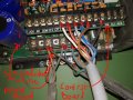
The semiconductor module is mounted to the back of the power board via through-holes into ground planes and thick traces, requiring a soldering gun to remove it (a normal iron won't touch it). The entire VFD must be disassembled to access it.
 

Attachments

MisterBill2

Joined Jan 23, 2018
27,748
OK, so the drive is physically a bit complex, and it does appear that the high power devices are all in one block. That alone does not cancel the value of a diagnosis, does it? The number of incorrect diagnosis that I have seen is impressive. On several occasions the failure was a poor solder joint that failed after a very few years. So it can still be worth looking at the power board, which I do not think has been done yet. Of course it is easier to say a device is not repairable and make the customer pay for a new one, just because it is less work for the service tech. But this is not a piece of production equipment on a long assembly line and so the TS is able to spend a few more minutes to determine what the failure actually is. Given the TS one comment that it did it once before for a little while, that does point towards a failed solder connection.
 

MaxHeadRoom

Joined Jul 18, 2013
30,716
They are asking $600 on ebay for the same model, USED!
You can get a new Hitachi model for just over $200.00
If a cursory inspection does not show anything up, the better option may be to bite the bullet for a newer model.! ;)
Max.
 

strantor

Joined Oct 3, 2010
6,875
OK, so the drive is physically a bit complex, and it does appear that the high power devices are all in one block. That alone does not cancel the value of a diagnosis, does it? The number of incorrect diagnosis that I have seen is impressive. On several occasions the failure was a poor solder joint that failed after a very few years. So it can still be worth looking at the power board, which I do not think has been done yet. Of course it is easier to say a device is not repairable and make the customer pay for a new one, just because it is less work for the service tech. But this is not a piece of production equipment on a long assembly line and so the TS is able to spend a few more minutes to determine what the failure actually is. Given the TS one comment that it did it once before for a little while, that does point towards a failed solder connection.
Fair enough, point taken. I am accustomed to declaring these things beyond salvation a bit earlier in the game than would be appropriate for a weekend warrior. Not because it's "easier" and not because I want to "make" my customers pay for extra parts, but because it's actually the right call for my customer. You saw the price of the VFD I recommended? My hourly rate is $150. If I spend more than an hour poking around on a PCB looking to confirm my own suspicions, I'm doing my customer a disservice. Even if I find the offending component in 5 minutes, it usually takes longer to get that component than it takes to get a new VFD, and the downtime eclipses the cost savings several fold. It usually doesn't make sense for me to start diagnosing components until the VFD in question is a 20+HP high end model. I carry around 5hp drives in my truck just for situations like this.

But is this a weekend warrior situation? Is this lathe used for hobby work? Or is TS losing money with this being down? What value does TS place on his time?
 

MisterBill2

Joined Jan 23, 2018
27,748
A close examination, even taking some voltage readings, will be an educational exercise even if it does not fix the fault. Gaining a bit of understanding is often useful. Not always useful immediately, but in the future.
 

MaxHeadRoom

Joined Jul 18, 2013
30,716
As a general rule, all the VFD's I have worked on, if any thing is off at all the VFD immediately goes in to fault, especially if this is a phase vector control version over a freq/hz model, the former should be the case for the OP's application.
As it appears to be running at 1/2 set speed, It might be worth checking the actual RPM, if the setting for either 2pole or 4 pole motor is off, it could account for it.
Max.
 

Thread Starter

blimp

Joined Feb 9, 2021
6
You have good points all of you, but please don't kill eachother over a lazy lathe! :)

If this was a machine used in our production I would have followed strantors advice a week ago, as troubleshooting and downtime would have ruined us. But as you said this is a weekend warrior case, and I'm kind of an electronics fan (Arduino and similar..) so troubleshooting is both educational and "cheap".

I didn't find the time for it yesterday, but I'll try again this weekend, as indoors troubleshooting is one of very few useful things to do in -30 degrees celcius.

Thank you guys for all the tips! Have a nice, peaceful weekend, and stay warm! :)
 

strantor

Joined Oct 3, 2010
6,875
as you said this is a weekend warrior case, and I'm kind of an electronics fan (Arduino and similar..) so troubleshooting is both educational and "cheap".
I had no idea. As this is your first and only thread on the forum and you expressed no other interest in electronics I assumed you were like many who just come here for help getting something working again and aren't interested in learning any more than they have to. If I had known, I would have had an entirely different approach. But now that I do, ...

What multimeter are you using?
 
Top