Facebook
 Google
 GitHub
 Linkedin
DickCappels
- Joined Aug 21, 2008
- 10,661
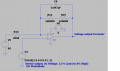
You are right - what looked like ground to me is a virtual ground elevated above the negative power supply connection.NO, look closer, that got me at first also. It is not ground, it is a line biased at half the supply voltage.
I withdraw my faulty observations.

")