OK,
The photo-transistor should not destroy the transistor, if it had done, when you unplugged the photo transistor pin #2 it would have not switched to 9v.
The 1k in series with the PT [photo transistor] would have limited the current into the transistors Base to a safe
What is the value of the capacitor on pins 6/7 of the 555.? and R4
As post #24 by Bertus explains, in the final circuit when you have it working OK, you should shield the PT from the room lighting.
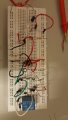
Ok. My bad. Now i reconnected the circuit. You can take a look my breadboard connection. But i havent connect the phototransistor yet.
R1 and C2 is 100kohms and 100macrofarad =11sec on time.
R4 i used 4.7kohms which connected to the collector.
Ok. My bad. Now i reconnected the circuit. You can take a look my breadboard connection. But i havent connect the phototransistor yet.
R1 and C2 is 100kohms and 100macrofarad =11sec on time.
R4 i used 4.7kohms which connected to the collector.
Realized a new problem here. When the ir emitter is emitted ir beam to phototransistor. There is few voltage from the collector to pin 2 . Thats why the trigger is continously in "high". But the led that i connected at the emitter side of phototransistor will still light up.
hi T,
I would recommend that you rebuild your project board using the simplified circuit of post #47.
When we have that simple working OK, we can deal with the PT problems and modify the circuit.
E
Post a photo shot of your board.
hi T,
I would recommend that you rebuild your project board using the simplified circuit of post #47.
When we have that simple working OK, we can deal with the PT problems and modify the circuit.
E
Post a photo shot of your board.
hi T,
I would recommend that you rebuild your project board using the simplified circuit of post #47.
When we have that simple working OK, we can deal with the PT problems and modify the circuit.
E
Post a photo shot of your board.
How about this? Will this be more easier? Want to make it at basement car park slot. When the car is parked between the infrared. Pin 4 will received voltage and the relay will turn on the light indicator. Isit ok?
hi T,
Of course we will help, its why we are here.
Don't give up on that 555 timer project, you will find that the 555 can be used in many ways, as its a popular IC.
When you start a new project build on a bread board, make the top most long row of sockets the plus voltage rail,
Link the second row from the top [ next to the plus voltage] a 0V rail and also link that to the to bottom row.
This will make your wiring shorter and easier to follow.
hi,
Build this part of the circuit first, it will give a continuous tone, it works
Note I have changed two component values to increase the sound frequency from about 300hZ to 3kHz, so that it will sound louder. R6 and C2
We will fit the opto next.
E
hi,
I assume your car bay is about 2 to 3 mtrs wide.?
This means the IR Emitter and Photo detector will be the 2 to 3 mtrs apart.
Using a DC continuous IR beam and a PT over that distance you will have problems due to the low level signal being picked up by the PT from the Emitter.
The garage ambient lighting will also be detected by the PT and it will over load the PT circuit.
You could use a lens at the Emitter and the PT, the PT could be mounted in a tube, the tube would block the ambient light.
A better solution is to drive the Emitter with a continuous pulses so that the PT circuit can amplify just those pulses, the PT tube would still be required.
E
Seems like the sound is okay. How about the ir emitter and phototransistor. I dont need to makes the ic555 monostable mode. Because i dont want to hold the sound or light even when the car is move out from the car park.
hi,
The sound should be approx 3kHz
On your latest circuit you have drawn a 'opto-coupler', so I guess you want to replace that with a photo detector and transistor, so I will post a diagram.
E
EDIT:
Build this part of the circuit on same board, do not connect to the 555.
Measure the voltages at Vpt and Vc, when the PT can see the IR beam and when it is blocked from the IR beam.
In that case would it not make a more reliable link to transmit the IR modulated at 38kHz and use a IR detector chip which will do a good job of rejecting interference. i.e. the system used by remote controls.
 Facebook
 Google
 GitHub
 Linkedin