MOSFET used for a heater PCB is always ON problem

Thread Starter

Hateyaall

Joined Jan 19, 2022
3
Hello everyone,
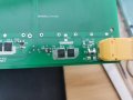
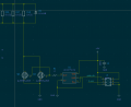
I made a PCB heater for a project but for some reason I got the MOSFET always on. I want to control it with PWM. I have a temp sensor on the heater and with it's data I want to be able to turn of and on the heater to achieve simpler version of a PID controller. The voltage to the gate is 4.7V ( 5V supply from the arduino Nano every). I am pretty new to designing electronics and I have probably done some mistake can anyone help me out a bit?
This is the data sheet of the MOSFET: https://store.comet.bg/download-file.php?id=7636
Thank you for your attention and time.
 

Attachments

Alec_t

Joined Sep 17, 2013
14,280
Welcome to AAC!
Did you buy the MOSFETs from a reputable source?
Do you have a 'scope to check if the gates are actually being pulled close to ground?
 

Thread Starter

Hateyaall

Joined Jan 19, 2022
3
Welcome to AAC!
Did you buy the MOSFETs from a reputable source?
Do you have a 'scope to check if the gates are actually being pulled close to ground?
I think that the source of the MOSFET is ok I've been working with this provider for quite some time. I picked those because they were laying around and were quite compatible with my application.
If I am measuring this right with the oscilloscope I have connected the probe to ground and measure the gates Voltage. When I start the heater I read about 4.7V at the gate. After the desired temp is reached the gate goes to 0V and the source goes to 500mV. I don't think that the latter should be happening.
On the photo below I have jumped over the fuse and the current sensor that i couldn't get due to the lack of parts and forgot to order the diodes because I thought I have them here. The MOSFETs to the left side of the picture are not part of that schematic and I still haven't reached the point to start testing them.
 

Attachments

DickCappels

Joined Aug 21, 2008
10,153
Elsewhere in the circuit: D5 may conduct for short periods of time if the wires from the controller the resistors and D5 are long, so it is a good idea to have there. The peak current D5 will see can be as high as the current flowing when the MOSFET turns off -when you have that fixed. You might want to check the current rating of D5,
 

Ian0

Joined Aug 7, 2020
9,667
the source goes to 500mV. I don't think that the latter should be happening.
I don’t see how it can be happening. you have the source connected to ground. If you are measuring between source and ground how can it be anything other than 0V?
 

Alec_t

Joined Sep 17, 2013
14,280
If the drain is 500mV when the gate is 0V you have either a dead MOSFET or a wiring error (as Crutschow said). Have you double-checked the pinout of the MOSFET?
 
Top