MOSFET speed for driving high current into LEDs

Thread Starter

ray242

Joined Nov 27, 2016
44
The voltage for the di/dt calculation (that which appears across the parasitic inductance) is the difference between the supply voltage and the LED drop, not the supply voltage.
You can add a resistor in series so you can use a higher supply voltage to reduce the di/dt value.
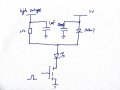
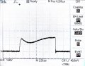
Hi Crutschow, thank you for your help last week. I have been trying to reduce the power dissipated in the resistor using the circuit below: I want the small capacitor to provide the speed at the beginning and the big capacitor to take over after the LED is switched on. However, the current from the small capacitor did not drop as I expected but seemed to have a bit of oscillation, as shown in the graph (only the small capacitor was used). Is it because of the small capacitance value so oscillation occurs more easily? Do you think this method would work with some adjustments or are there other possible ways to limit the power dissipation?

Thank you!
 

Attachments

crutschow

Joined Mar 14, 2008
34,469
Add a larger resistor between the high voltage and the capacitor and adjust the 1Ω resistor value to get the desired rise time and waveform.
 

Thread Starter

ray242

Joined Nov 27, 2016
44
Add a larger resistor between the high voltage and the capacitor and adjust the 1Ω resistor value to get the desired rise time and waveform.
Is that for limiting the current from the high voltage? I already limited the current to 50mA, is it still too much?

Thank you.
 

Thread Starter

ray242

Joined Nov 27, 2016
44
Yes.
If you don't need the resistor for that, then you likely need to experiment with the value of the capacitor and the 1Ω resistor to get the waveform you want.
It turned out that my power supply can still provide 20A even though I set the current limit to a very low value:oops:
Thank you!
 

MrAl

Joined Jun 17, 2014
11,496
Hello,

I would bet there is something fundamentally wrong with the circuit or setup.

First, the waveforms in the first post show the drain voltage RISING as the input gate voltage goes high. How can that be possible? When the mosfet turns on, the drain voltage should be ramping downward. This means we have yet to see the response of the mosfet to the gate drive signal.

Second, how did you estimate the inductance? The inductance is the self inductance of the loop formed by the mosfet, capacitor, LED's and connecting wires. If you draw a picture of your setup we can go over the estimate.

Third, what is the ESR of the capacitor? This is a very very important aspect of the circuit. If the ESR is high enough it's like not having a cap there at all for short time periods, when that's the whole point of having it there in the first place.

So...
1. Try to show the true waveforms.
2. Show how you estimated the loop self inductance; show your lengths around the mosfet/LEDs/Cap circuit.
3. Find the ESR of the cap and report that also.

In this way we can look deeper into this problem.
 
Top