 Facebook
 Google
 GitHub
 Linkedin
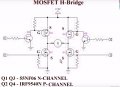
I am working to develop a 12v dc/ac inverter with 4 mosfets 2 pchannel irf9540 (High side and 2 nchannel 55nf06(Low side) as in circuit.
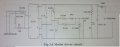
driver circuit - 4 independent drivers input from arduino isolated by tlp250 and amplifies by a tottem pole BJT circuit as shown in figure.
TLP 250 supply is provided feom a 230/12v transformer.
2 pulses with phase shift of 180 degree and amplitude about 6v were generated to gates. gate pulses to Q1 AND Q3 are identical and Q2 and Q4 are identical.
frequency of pulses 50Hz Ton = 10ms.
I am facing some problem , while connecting the circuit to 12v Vcc THE 2 pchannel mosfets are highly heating and circuit is not working.
employed 10k bleeding resistors.
PLZ help..
Attachments
-
 127.9 KB Views: 26
 -
 83.8 KB Views: 25


