Facebook
 Google
 GitHub
 Linkedin
Hello All,
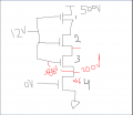
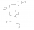
wondering whether we can connect MOSFETS ( which are rated for 500V) in series to increase voltage output. I tried simulation in LTSPICE. I connected 3 MOSFETS in series and I am observing decrease in output voltage. I have attached configuration picture.
Does over all output voltage increases when FETS are connected in series ??
Please let me know.
Attachments
-
 11.7 KB Views: 66