Facebook
 Google
 GitHub
 Linkedin
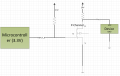
I got stuck trying to figure out how hot my mosfet will get without a heatsink. Unsure what i'm doing wrong.
Trying to get temp under continuous current. This isn't a switching condition.
Chip:
NXP PH4030AL
https://www.digchip.com/datasheets/download_datasheet.php?id=4426733&part-number=PH4030AL,115
ChatGPT tells me:
To calculate the heat dissipation of a MOSFET without a heatsink, you can use the following steps:
Here's my math.
Calculate the RDS(on) resistance from the drop in voltage across the MOSFET and current.
I^2 * RDSon = watts heat
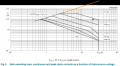
Multiply the amount of heat the device dissipates by the junction-to-case thermal resistance.
W * Rth(j-mb)
aka thetaJC (correct?)
Subtract the temperature rise from the maximum junction temperature to get the maximum case temperature.
Tj - temp_rise
eg
175C - 6C = 169C?
Zth(jc) = (Tj - Tc)/P =
(4.9 - ...?
Trying to get temp under continuous current. This isn't a switching condition.
Chip:
NXP PH4030AL
https://www.digchip.com/datasheets/download_datasheet.php?id=4426733&part-number=PH4030AL,115
ChatGPT tells me:
To calculate the heat dissipation of a MOSFET without a heatsink, you can use the following steps:
- Calculate the RDS(on) resistance from the drop in voltage across the MOSFET and current.
- Multiply the amount of heat the device dissipates by the junction-to-case thermal resistance.
- Subtract the temperature rise from the maximum junction temperature to get the maximum case temperature.
Here's my math.
Calculate the RDS(on) resistance from the drop in voltage across the MOSFET and current.
I^2 * RDSon = watts heat
10A ^2 * 3.3 mOhms =
100 * .0033 =
.33 watts
Multiply the amount of heat the device dissipates by the junction-to-case thermal resistance.
W * Rth(j-mb)
aka thetaJC (correct?)
.33 W * 1.82 = 6 degrees C?
Subtract the temperature rise from the maximum junction temperature to get the maximum case temperature.
Tj - temp_rise
eg
175C - 6C = 169C?
Zth(jc) = (Tj - Tc)/P =
(4.9 - ...?
Last edited: