 Facebook
 Google
 GitHub
 Linkedin
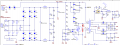
The circuit attached below is from Texas Instruments: http://www.ti.com/tool/TIDA-00173
My question is: what is the voltage at the gate of the MOSFET Q1? It is defined by the 12V zener? Is it okay to say that, for example, if DC bus voltage is 1000V, then the zener current would be (1000-12)/(470k*6) = ~350 uA? If the FET is off, the gate voltage is clamped by D15 and D16 to ~ 800V, but isn't it too high for the gate?
My question is: what is the voltage at the gate of the MOSFET Q1? It is defined by the 12V zener? Is it okay to say that, for example, if DC bus voltage is 1000V, then the zener current would be (1000-12)/(470k*6) = ~350 uA? If the FET is off, the gate voltage is clamped by D15 and D16 to ~ 800V, but isn't it too high for the gate?
Attachments
-
 85.4 KB Views: 68


