MOSFET as a load and something is going on i don't understand.

Thread Starter

Sebestyén Kárpáti

Joined Oct 14, 2017
7
I use car headlamps.
Alright. I have changed the gate drive of the FET from Voltage to PWM so it is either open or closed rather than half open. I can reach 10 amps before the heatsink can't keep up (CPU heatsink with fan). But I still don't get it. What difference does it make if I have resistive load before the FET? the 25 Amps will still pass through it how will it reduce the heat generated on the FET. Or will the voltage drop before it gets to the FET on the resistive load? Is that the idea? How about using more than one FET to share the load?
 

recklessrog

Joined May 23, 2013
985
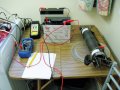
Here is the method I am currently using to monitor discharge of rejuvernated gell cell batteries. The rheostat is over 70 years old and was used to control the speed of an industrial motor. It has been one of my most useful pieces of test equipment.

P1010008 1.jpg
 

Attachments

Thread Starter

Sebestyén Kárpáti

Joined Oct 14, 2017
7
Here is the method I am currently using to monitor discharge of rejuvernated gell cell batteries. The rheostat is over 70 years old and was used to control the speed of an industrial motor. It has been one of my most useful pieces of test equipment.

View attachment 146225

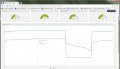
I like that. That is the basic idea. I'm just trying to make it all automatic/ or just overly complicated :) When you connect the battery, first it will be charged by solar panels, when the battery is fully charged, the solar panels will be disconnected and after one hour of rest period the load test will commence. Set current will be maintained regardless of the battery voltage dropping.When the battery reaches 10.5 volt, it will send an email/sms, and start recharging the batteries. When the batteries will be fully charged again, it will send an email/sms to let you know the battery is fully charged but it will not do another load test cycle. It will be be accessible online to monitor the process and all other data (temperatures, currents, voltages...). There are 2 levels of protections in the PLC for over current, temperature.
 

ebp

Joined Feb 8, 2018
2,332
Tubular ceramic resistors rated at 225 W are reasonably priced and generally easy to obtain and operate without a heatsink, though they will get very hot at full power without forced air cooling. They aren't damaged by operating at full power in free air. They are moderately inductive, so they aren't suitable for high frequency work, but would be fine for battery testing. You can buy mounting "clips" for them. There is not a huge choice of resistances available, so that may be an issue. There are variable types that have a sliding tap. To move the tap you have to loosen a screw, so you can't adjust them while under load. When you use only part of the resistor you can only dissipate proportional power. For example, if you had a 2 ohm 225 W resistor set with the slider at 1.5 ohms, you could only dissipate 1.5/2 * 225 = 169 W. These resistors will withstand several times their rated power for a short time.

Be aware that PWM loading a battery, without inductance to smooth the current, is going you yield results that differ from the same average load with low current ripple, especially if the RMS to average current ratio is high.


I think that ap note from Linear was the last one Jim Williams completed before he died. He produced some of the best analog applications notes in the industry.

Incandescent lamps can be OK, as long as the issues OBW pointed out are considered. It isn't that the tempco is huge (not a lot higher than copper's), it's that the filament gets so very hot. Lots of relays have a "tungsten" rating. Cold/hot current was especially brutal for 3400K photoflood lamps that had a 4 hour life rating. When operated on AC there is actually measurable phase difference between the voltage and the current in ordinary tungsten lamps.
Math, you call that? Math? That's arithmetic. :)
 

Thread Starter

Sebestyén Kárpáti

Joined Oct 14, 2017
7
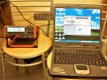
All right, here's the final product. Ended up using a IXYS IXFB132N50P3 N-channel MOSFET, 132 A, 500 V HiperFET, Polar3, 3-Pin PLUS264 which has a power dissipation of 1.9kW. It is being driven by voltage not PWM but it can handle the 25A (actually 20 max as a light bulb is connected in parrallel that draws 5 amps and when the FET temperature reaches 80 degree celsius it is being switched on sharing the load with the FET. IMG_20180403_133207[1].jpg
 

Attachments

ebeowulf17

Joined Aug 12, 2014
3,307
I don't see how you can do much at all in electronics without at least that much math; without it, all you can rely on is guesswork and superstition.
I know this is a very old post, but I just came across it.

I think you'd be surprised how much design work gets done with guesswork and superstition, even in commercial settings with regulatory requirements, etc. I'm hardly surprised that there are hordes of hobbyists working this way.

Also, as for the simplicity of the math, for many people it's not the complexity of the basic math, it's understanding the application - when to use which formula, etc. Many of the applications in electronics that I've seen remind me of all the word problem drills in high school. Many of my classmates could do all the math on one of those "two trains approaching..." word problems if you handed them all the formulas, but they couldn't translate the word problem into formulas for themselves. It's a different art, or at least a different flavor of it.
 

OBW0549

Joined Mar 2, 2015
3,565
I think you'd be surprised how much design work gets done with guesswork and superstition, even in commercial settings with regulatory requirements, etc. I'm hardly surprised that there are hordes of hobbyists working this way.
Oh, I'm not really all that surprised at either one.

Regarding hobbyists, this phrase always elicits a groan:

"I found this circuit on the Internet..."

Also, as for the simplicity of the math, for many people it's not the complexity of the basic math, it's understanding the application - when to use which formula, etc. Many of the applications in electronics that I've seen remind me of all the word problem drills in high school. Many of my classmates could do all the math on one of those "two trains approaching..." word problems if you handed them all the formulas, but they couldn't translate the word problem into formulas for themselves. It's a different art, or at least a different flavor of it.
Agreed, that's a big part of the problem in many cases.
 
Top