Facebook
 Google
 GitHub
 Linkedin
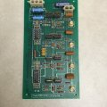
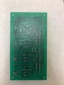
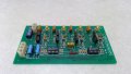
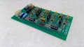
I'm trying to problem solve this circuit. I know this amplifier was working correctly and originally it took 0-5V and output 0-125V. The particular type of circuit I am unsure of, but I think it is a cascading amplifier circuit. The problem is that when I input ~2.5V the output is 109V (should be ~50V) and the maximum input it will take is 0-3V, so the ratio is incorrect. I believe the issue stemmed from when I put 5.28V into one of the input channels. I have another board that I mapped out to compare voltages at different points. At the LF147 IC I wasn't able to see any changes in voltage between the good board and the bad board; I attached a picture of the bad board with voltages mapped. Additionally, I attached a schematic for one of the channels. The only difference I found was at the drain of the MOSFETs (109V), but due to the way they are connected, I am having difficulty pinpointing the problem. I'm finding it odd that all four channels of this circuit are affected. Any help would be appreciated, let me know if I can clarify or include more information to provide a better sense of the situation.
I attached the datasheets for both the amplifier IC and the MOSFETs.
I attached the datasheets for both the amplifier IC and the MOSFETs.
Attachments
-
 1.5 MB Views: 31
 -
283.4 KB Views: 8
-
1.7 MB Views: 4
-
 1 MB Views: 24