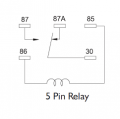
If he connects to pin 87 (NC), then to turn the lights off, current must flow through the coil. I’d guess the lights would be off more than on, which would draw “extra” current.
I’ll take your word for it. I admitted that I was unfamiliar with pin numbering. The source from my research (likely incorrect in light of your post) said that pin 87 was NC.
Ultimately, the NO contact on the relay is the one that should connect to the light bar.
So @blavery, connect the light bar to the NO (Normally Open) contact.
I would tend to believe pin 87 is NO. What's the use of having a fan, fuel or horn relay (for example) that you have to turn the relay ON to turn those devices OFF? 30 & 87 should be open at normal resting mode and only conducting when pins 85 & 86 are powered. That's what a relay is supposed to do.
As for the other parts of your wiring question, the switch illumination and the indicator, going back to my illustration in post #2 you're going to have to feed power back to those parts of the switch, which means IF (big "IF" there) but IF the dash wiring is CAN BUS then you're going to have to cut some wiring and splice in according to your needs. Decisions on how to approach that part of it will require further consideration and discovery as to what each wire is doing and why. Also whether cutting those connections could interrupt other functionings of the system.
Agreed, I have been able to splice into wiring for the illumination from an adjacent switch and it seems to work just fine. I will have to feed power back to the switch for the indicator based on your illustration from post #2. Can't do that until I get the parts that are on order, but that's the current plan.
I'm getting both a 4 pin NO relay and a 5 pin relay and will dig into it a bit more when I get the components.
In a 4 pin automotive relay pin 87 can be either NO or NC. Four pin automotive relays come in both configurations. In a five pin relay, pin 87 is the NO contact.
I don’t use them often so that is why I waffled at first, then subsequently referred to the pins by function instead of number. In checking assignments for my first post, I chose an incorrect reference just to add to the confusion!
The TS should use a NO contact in his application.
IMHO, I think the idea presented in post #6 is the best one. You can use the module to operate this relay (which is rated for 15A), which then can switch the light bar on/off with successive presses of the pushbutton. Everything is wired as in this diagram: View attachment 295398
@djsfantasi this ended up working. Thank you. I’m wondering what keeps the higher amperage current from running through the module and burning it up? It looks like the 11.8A of the light bar would try to go through the module rather than around.
@djsfantasi this ended up working. Thank you. I’m wondering what keeps the higher amperage current from running through the module and burning it up? It looks like the 11.8A of the light bar would try to go through the module rather than around.
The module is totally isolated from the 11,8 amps by the relay. The current for the light bar is switched by the relay contacts (which are rated for 15A). None of that current can get to the module. The contacts are what carries the current “around” the module.
Note the module contains a relay as well. So the module relay switches the (low current) automotive relay which switches the high current light bar.
I am trying to do the same thing with the same module and I'm testing them on the bench and they work for a few minutes. The red LED is powered and the test button makes the relay click and the light term green (the remore switch does the same) and the contacts Have continuity. I'm testing it with a battery charger as power source set to 6 amps. Am i doing something wrong? Already went through 4 modules

 Facebook
 Google
 GitHub
 Linkedin