MOD-60 counter with stop/start and reset buttons

Thread Starter

XxdeadshotxX

Joined Nov 8, 2019
28
HI all

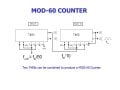
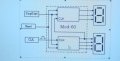
I am given an assignment by my lecture. We are using 74LS93, 74LS00 and 74LS32 ICs to build a 60 seconds stopwatch. . I have some problem building MOD-60 counter from 00 - 59 in multisim. I have connect the these two ICs to two 7 segment LED common Anode.

I do not know how to add in stop/start and reset buttons also. The reset button switch will clear or reset the mod-60 counter to 00 when activated. ie, 00 until it is started again through the use of the start/stop switch.

when the mod-60 value is running , activating the start/stop switch will stop the counter at its current count value, ie, 40, which indicates a time lapse of 40 seconds from the start. Reactivating this same switch will cause the mod-60 counter to resume from this previously stopped value.

We are given other F/F IC like 74LS74 and 74LS112

Pls help me!!

thx
 

bertus

Joined Apr 5, 2008
22,270
Hello,

What is the size in pixels?
It can be that a side of larger as 1280 pixels will be rejected.

Bertus
 

bertus

Joined Apr 5, 2008
22,270
Hello,

I already notified the technical admin about the issue of uploading pictures.
Can you rescale the picture to 1280 a side?
This can likely be done in a paint-like program.

Bertus
 

ericgibbs

Joined Jan 29, 2010
18,766
hi,
Is this summary of actions correct.?
If yes, first show your idea how to Reset to '00'

E

Summary:
1 Reset Counter to '00'
2. Start/Stop Counter.
3.Count from 0 Sec thru 59 Sec and Stop or Auto restart at '00'
 

LesJones

Joined Jan 8, 2017
4,174
That is just a block diagram. What is inside the two blocks in the box surrounded by the dotted line ? Are you ONLY allowed to use the ICs listed in post #1 ? If so you will have to design a decoder to drive the 7 segment displays. (This would normally be done with a decoder/driver IC.)

Les.
 

ericgibbs

Joined Jan 29, 2010
18,766
hi,
As I read the TS's project, its a simulation in Multisim, no indication of a visual numeric display.?

E

Update:
This may help as a starting point, edit as required.
 

Attachments

Last edited:

Thread Starter

XxdeadshotxX

Joined Nov 8, 2019
28
ye
That is just a block diagram. What is inside the two blocks in the box surrounded by the dotted line ? Are you ONLY allowed to use the ICs listed in post #1 ? If so you will have to design a decoder to drive the 7 segment displays. (This would normally be done with a decoder/driver IC.)

Les.
Yes. Everything that is provided are listed in post #1
 

ericgibbs

Joined Jan 29, 2010
18,766
hi X,
As this is Homework we need to see your attempt at connecting the IC's in the project, we can then advise you.
E
BTW:
The LS193 is a alternative counter, but you should use the the type given by your tutor.
 

Thread Starter

XxdeadshotxX

Joined Nov 8, 2019
28
hi X,
As this is Homework we need to see your attempt at connecting the IC's in the project, we can then advise you.
E
BTW:
The LS193 is a alternative counter, but you should use the the type given by your tutor.
Yes sir, do not spoon feed me. i will go home later and try to come out with something with multisim:)
 

Thread Starter

XxdeadshotxX

Joined Nov 8, 2019
28
hi X,
As this is Homework we need to see your attempt at connecting the IC's in the project, we can then advise you.
E
BTW:
The LS193 is a alternative counter, but you should use the the type given by your tutor.
Hi i want to ask if i need to have clk pulses do i connect vcc to it also or there is other connections?
 
Top