MOD-60 counter with stop/start and reset buttons

dl324

Joined Mar 30, 2015
16,943
i want to ask if i need to have clk pulses do i connect vcc to it also or there is other connections?
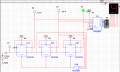
The schematic you posted in #7 shows a clock and no connections to VCC (other than power to the IC's). You have a mod 60 counter and all you need to do is add pause/restart and reset. It shouldn't take you more than a few minutes to do that.
 

Thread Starter

XxdeadshotxX

Joined Nov 8, 2019
28
Hi this is my design for the MOD 6 counter but for some reasons my multisim keeps displaying simulation error and i don't know what to do. Please advice thx
 

Attachments

Thread Starter

XxdeadshotxX

Joined Nov 8, 2019
28
What is the error message?

Why are you using 74LS74? Your original post said you were supposed to use:
Hi dennis, we are suppose to use a 74LS74 and a 74LS112 F/F IC to design the whole thing and the other are just basic gates like NAND gates binary counter and OR gates:) The error message is:
------ Checking SPICE netlist for Circuit2 - 2019-11-10 23:22:44 ------
SPICE Netlist Error in schematic RefDes 'u3', element 'au3_b[13 du3.not2pr 15 10]': Invalid component name 'au3_b[13 du3.not2pr 15 10]'
SPICE Netlist Error in schematic RefDes 'u3', element '<unknown>': Due to errors, the component 'au3_b[13 du3.not2pr 15 10]' has been omitted from the simulation
SPICE Netlist Error in schematic RefDes 'u2', element 'au2_b[10 du2.not2pr 15 9]': Invalid component name 'au2_b[10 du2.not2pr 15 9]'
SPICE Netlist Error in schematic RefDes 'u2', element '<unknown>': Due to errors, the component 'au2_b[10 du2.not2pr 15 9]' has been omitted from the simulation
======= SPICE Netlist check completed, 4 error(s), 0 warning(s) =======

A simulation error has occurred. Would you like to run the Convergence Assistant to attempt to resolve this problem automatically?
 

dl324

Joined Mar 30, 2015
16,943
Hi dennis, we are suppose to use a 74LS74 and a 74LS112 F/F IC to design the whole thing and the other are just basic gates like NAND gates binary counter and OR gates
This conflicts with your first post. If you can use a binary counter, why aren't you using them?
A simulation error has occurred. Would you like to run the Convergence Assistant to attempt to resolve this problem automatically?
It seems like it's complaining about the second flip flop in U2 and U3. Omitting them shouldn't affect the circuit.

Have you tried using the convergence assistant?

If you can't figure it out, start over.
 

Thread Starter

XxdeadshotxX

Joined Nov 8, 2019
28
This conflicts with your first post. If you can use a binary counter, why aren't you using them?
It seems like it's complaining about the second flip flop in U2 and U3. Omitting them shouldn't affect the circuit.

Have you tried using the convergence assistant?

If you can't figure it out, start over.
The convergence assistance didnt do anything much. Guess i will start over:(
 

dl324

Joined Mar 30, 2015
16,943
The convergence assistance didnt do anything much. Guess i will start over:(
Starting over will likely be faster than trying to debug.

I never liked Multisim. Components can look like they're connected when they aren't. I spent a lot of time dragging components to make sure all of the wires were really connected.
 

Thread Starter

XxdeadshotxX

Joined Nov 8, 2019
28
Starting over will likely be faster than trying to debug.

I never liked Multisim. Components can look like they're connected when they aren't. I spent a lot of time dragging components to make sure all of the wires were really connected.
But we are required to use multisim to submit our work:(
 

dl324

Joined Mar 30, 2015
16,943
i have no idea on how to do it.
Were you able to get your modulo 6 counter to work?

Here's the relevant portion of your schematic for those who prefer not to download largish images.
1573824569674.JPG

Are you allowed to use the 74LS93 datasheet as a reference?

You've been working on this for a week. What is your deadline?
 

dl324

Joined Mar 30, 2015
16,943
i got this design and it works but
Here's your circuit redrawn with some style:
1573924729703.png

Instead of doing screen shots, you could print to PDF and get rid of the grid and moire patterns. At the very minimum, you could do screen grabs of the relevant portion (don't recall if Multisim lets you turn off the grid, but it doesn't show up when printing). I haven't used my version of MultisimBLUE for years and found that it became unsupported a couple years ago...

EDIT: Here's part of an up/down 24 hour clock design I did for someone on AAC a few years ago:
1573924770177.png
This is essentially an up/down modulo 60 counter with start/pause and reset.
 
Last edited:

Thread Starter

XxdeadshotxX

Joined Nov 8, 2019
28
Here's your circuit redrawn with some style:
View attachment 191599

Instead of doing screen shots, you could print to PDF and get rid of the grid and moire patterns. At the very minimum, you could do screen grabs of the relevant portion (don't recall if Multisim lets you turn off the grid, but it doesn't show up when printing). I haven't used my version of MultisimBLUE for years and found that it became unsupported a couple years ago...

EDIT: Here's part of an up/down 24 hour clock design I did for someone on AAC a few years ago:
View attachment 191600
This is essentially an up/down modulo 60 counter with start/pause and reset.
i cant use this because we need to use D latch for our start/stop thats y im stuck:( I actually figured out a way to do start/stop without the use of D latch but my lecturer rejected the design:( sp he ask the whole class to use D latch in the end
 

dl324

Joined Mar 30, 2015
16,943
i cant use this because we need to use D latch for our start/stop thats y im stuck
I didn't intend for you to use any counters. I was just showing you an implementation like the one you got working that was drawn more neatly. And then a design I did in MultisimBLUE that implemented a mod 60 counter using different counters, but drawn neatly.

Are you sure he said to use latches? 74LS74 is a D flip flop, not a latch.
 

Thread Starter

XxdeadshotxX

Joined Nov 8, 2019
28
I didn't intend for you to use any counters. I was just showing you an implementation like the one you got working that was drawn more neatly. And then a design I did in MultisimBLUE that implemented a mod 60 counter using different counters, but drawn neatly.

Are you sure he said to use latches? 74LS74 is a D flip flop, not a latch.
He told us to use 74LS74
 
Top