moc7811 speed sensor...

Thread Starter

onlyvinod56

Joined Oct 14, 2008
369
hi
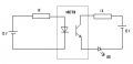
Iam using moc7811 for my project to sense the speed.
I observed that it has 4 terminals.
Two for detector and two for emitter.
My doubt is, What is the possible voltage to be applied for the emitter?
I connected to 12v in series with 1K. it was damaged.
thanQ
 

hgmjr

Joined Jan 28, 2005
9,027
The hook should as you describe it should not have cause the failure of the unit.

It would be easier to tell where things went wrong if you would post a schematic of the circuit that you are working with.

hgmjr
 

Thread Starter

onlyvinod56

Joined Oct 14, 2008
369
The hook should as you describe it should not have cause the failure of the unit.

It would be easier to tell where things went wrong if you would post a schematic of the circuit that you are working with.

hgmjr
Hi
here is the schematic. sorry, i dont know. I think may be i had increased the 12v.thats why it may damaged.
anyways, is this the proper way to test the sensor?
is there any other way to connect it.
I want to measure the speed and to display it on a 7 segment unit.
Is there any circuit available? i dont want to use micro controller.
plz forward me link for the speed measurement circuit.
thanQ
 

Attachments

SgtWookie

Joined Jul 17, 2007
22,230
Do you measure any voltage across the left resistor? If so, the emitter is not open.

I don't know what the maximum reverse voltage is for the emitter; I can't find a datasheet for it. However, IR LED's typically have a pretty low forward voltage; perhaps 1.2v to 1.5v. Maximum reverse voltage is likely around 5v. If you accidentally connected the 12v in reverse across the emitter, you could have destroyed it.

If you have another of these MOC7811 emitter/detector pairs around, I suggest that you experiment using only low voltages. A pair of "AA" or "D" cells in series (for 3v total) with a current limiting resistor of 90 Ohms should give an IR emitter with a Vf of 1.2v 20mA current. That way, if you should connect the emitter backwards, the 3v potential across the batteries won't destroy it.

As far as an LED counter circuit, see the attached. It simply counts up. U1 is a Hall-effect sensor, but you could substitute the detector side of your MOC7811. If you wanted to display RPM, you would have to add a timer circuit to control the counter reset and load enable on IC1.

If you need more than 3 digits (RPM>999), you could cascade another complete circuit using the OF (overflow) output of IC1 to clock it.
 

Attachments

Last edited:

Thread Starter

onlyvinod56

Joined Oct 14, 2008
369
Do you measure any voltage across the left resistor? If so, the emitter is not open.

I don't know what the maximum reverse voltage is for the emitter; I can't find a datasheet for it. However, IR LED's typically have a pretty low forward voltage; perhaps 1.2v to 1.5v. Maximum reverse voltage is likely around 5v. If you accidentally connected the 12v in reverse across the emitter, you could have destroyed it.

If you have another of these MOC7811 emitter/detector pairs around, I suggest that you experiment using only low voltages. A pair of "AA" or "D" cells with a current limiting resistor of 90 Ohms should give an IR emitter with a Vf of 1.2v 20mA current. That way, if you should connect the emitter backwards, you won't destroy it.

As far as an LED counter circuit, see the attached. It simply counts up. U1 is a Hall-effect sensor, but you could substitute the detector side of your MOC7811. If you wanted to display RPM, you would have to add a timer circuit to control the counter reset and load enable on IC1.

If you need more than 3 digits (RPM>999), you could cascade another complete circuit using the OF (overflow) output of IC1 to clock it.
Hi,
Thanks for ur advise. I just got the result of moc7811. thanQ.
Regarding the speed display, what i understud from ur attachment is, it simply counts the number of pulses and displaying.

can u please tell me in detail about the timer for reset and enable the circuit.
ThanQ
 

SgtWookie

Joined Jul 17, 2007
22,230
I don't know how accurate you need this to be.

I don't know what RPM range you're trying to measure.

If you just want a "ballpark" idea of the RPM, you could use a 555-type timer circuit. You could be off by quite a bit.
If you want it to be fairly accurate, you would need to use a crystal oscillator circuit.
If you want it to be really accurate, you would need to use an OCXO (oven controlled crystal oscillator) circuit.
Cost and complexity can get out of hand pretty fast.

Basically, the counter is allowed to run for a fixed period of time, counting pulses from the MOC7811.
At the end of that period of time, the Disable (IC1 pin 11) needs to be raised to Vdd, and Latch Enable (IC1 pin 10) need to briefly be raised to Vdd, and lowered back to Vss (ground).
Then the RESET pin ((IC1 pin 13) needs to be briefly raised to Vdd and lowered back to Vss to reset the counters. The count will remain latched into the outputs, and displayed on the 7-segment LED displays.
Once Disable (IC1 pin 11) is dropped back to Vss (GND) the count will begin again.

If you count input pulses for 6 seconds (1 pulse per revolution), the display will be RPM/10; so an RPM of 4321 would be displayed as 432.
If you used a hex nut as a reflector, you could get 6 pulses per revolution; counting pulses for 1 second would give you RPM/10 display again - but your wait time to display would be less.
 
Last edited:

SgtWookie

Joined Jul 17, 2007
22,230
This project would likely be much easier to build if you used a microcontroller connected to an LCD display.
The hard part would then be the programming.
 
Top