Facebook
 Google
 GitHub
 Linkedin
Hello,
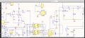
I am in the conceptual stage of creating an amplifier that will boost mixed signal input.
I tried using a class A amplifier with a 2n4401, I get good amplification , but agter 60khz, the amplitude decreases, at 130Khz, I get 50% of the desired amplitude.
How can I fix this ? I need the full amplitude up to 20mhz. Any special circuit design ? opamp ?
any help would be appreciated.
ken