 Facebook
 Google
 GitHub
 Linkedin
I am developing a PCB for an analogue sensing application. It uses the internal ADC on a PSoC3. As usual, the application is very space constrained (11mm x 21mm), so I have had to make some compromises in the PCB layout which I would not have done on a larger PCB.
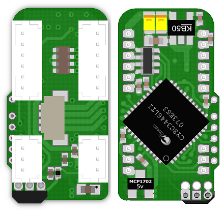
The board is supplied by regulated 6v, and contains two 5v linear regulators. An MCP1702 for the digital supply, and an MIC5205 for the analogue supply. The board is sensing five A1324 Hall effect sensors. Each Hall effect output signal is filtered by a 100nF + 1k RC filter. One sensor is on the PCB itself (bottom right). The other 4 plug into the right hand 6-pin connector.
The chip is acting as an SPI slave, but ADC samples are always taken between SPI transactions, so the SPI should not interfere with the analogue signals.
Sadly, I am still seeing some noise (about 1.5 LSB at 12-bits) on the analogue signals, and I wonder if there is anything I could have done differently in the layout to improve it.

Other PCB designs I have done using the MCP3208, and the same dual 5v supplies, same sensors, and same RC filters have achieved no noticeable noise at 12 bits.
The ADC on the PSoC3 is a delta sigma type. This version of the PSoC is limited to 12 bits, but another part number has a 16-bit ADC (although with a lower sample rate).
I do care about the noise, and would really like to push it a bit further towards 12 ENOB. The reason is not accuracy, but velocity measurement. Currently this level of noise is making it impossible to do accurate position and velocity control on a robot.
Schematic. Sorry it's a bit cramped, but you can just about read the values.

The board is supplied by regulated 6v, and contains two 5v linear regulators. An MCP1702 for the digital supply, and an MIC5205 for the analogue supply. The board is sensing five A1324 Hall effect sensors. Each Hall effect output signal is filtered by a 100nF + 1k RC filter. One sensor is on the PCB itself (bottom right). The other 4 plug into the right hand 6-pin connector.
The chip is acting as an SPI slave, but ADC samples are always taken between SPI transactions, so the SPI should not interfere with the analogue signals.
Sadly, I am still seeing some noise (about 1.5 LSB at 12-bits) on the analogue signals, and I wonder if there is anything I could have done differently in the layout to improve it.
Other PCB designs I have done using the MCP3208, and the same dual 5v supplies, same sensors, and same RC filters have achieved no noticeable noise at 12 bits.
The ADC on the PSoC3 is a delta sigma type. This version of the PSoC is limited to 12 bits, but another part number has a 16-bit ADC (although with a lower sample rate).
I do care about the noise, and would really like to push it a bit further towards 12 ENOB. The reason is not accuracy, but velocity measurement. Currently this level of noise is making it impossible to do accurate position and velocity control on a robot.
Schematic. Sorry it's a bit cramped, but you can just about read the values.


