Facebook
 Google
 GitHub
 Linkedin
Hi to all.
Hope i am welcome in this community?
Been member on some other forums but unfortunately didn't get what i search for (team play or leak of help)
Hope that at last this will be what i am searching for according to activity, views and replays on threads.
I want to mention that i am good skilled on Mobile (flashing - unlocking) and PC software diagnose repair with over 10 years but non skilled on PCB Repair. I am not totally beginner on PCB Repair , so maybe this will make things easier to get help from you guys. Those was few words about me.
Going strict to the subject (will post screenshots so members can easy understand what i am looking for)
Don't say buy a new one. I Know its cheap part but point is that i want to learn")
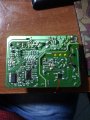
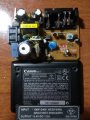
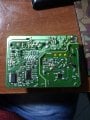
I Have Canon 10D charger with Input 110v-240v AC50/60Hz and Output 8.4V DC 1.2A
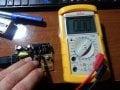
Voltage with connected cord on PCB is 235V so obviously current, cord and connector on board seems to be ok. But when i measure battery output connector it gives me 0.00V and sometimes 0.06V. I will avoid talking of mine opinion where can be problem (power reductor or what ever) because as i say i am beginner for diagnosing those problems. So Please check attached photos and tell me which part's or should i check.
If somehow i make post in wrong section kindly asking moderators to move it at right section
Thank you in Advance
Hope i am welcome in this community?
Been member on some other forums but unfortunately didn't get what i search for (team play or leak of help)
Hope that at last this will be what i am searching for according to activity, views and replays on threads.
I want to mention that i am good skilled on Mobile (flashing - unlocking) and PC software diagnose repair with over 10 years but non skilled on PCB Repair. I am not totally beginner on PCB Repair , so maybe this will make things easier to get help from you guys. Those was few words about me.
Going strict to the subject (will post screenshots so members can easy understand what i am looking for)
Don't say buy a new one. I Know its cheap part but point is that i want to learn
I Have Canon 10D charger with Input 110v-240v AC50/60Hz and Output 8.4V DC 1.2A
Voltage with connected cord on PCB is 235V so obviously current, cord and connector on board seems to be ok. But when i measure battery output connector it gives me 0.00V and sometimes 0.06V. I will avoid talking of mine opinion where can be problem (power reductor or what ever) because as i say i am beginner for diagnosing those problems. So Please check attached photos and tell me which part's or should i check.
If somehow i make post in wrong section kindly asking moderators to move it at right section
Thank you in Advance
Attachments
-
 974.2 KB Views: 58
 -
 866.4 KB Views: 50
 -
 925 KB Views: 52
 -
 850.3 KB Views: 48