 Facebook
 Google
 GitHub
 Linkedin
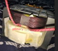
I have used many of these transformers and find them great for cheap high current power supplies.But in your photo the primary is the top red heavy copper and the secondary your want to cut out in on the bottom under the white insulation insulation.
A non regulated DC supply would be easy and all you need is a large bridge rectifier,no large electros as they increase the voltage when unloaded.You need to check your transformer power rating first before calculating current at what volts.As someone allready said it is easy to check voltage per turn ,just put a few turns on where you cut the secondary off of insulated wire and measure the AC volts,then work out your turns needed.When that is done you can work out how thick of wire you can install for your max current.
My example I use 5-6 turns of 6-8mm wire for 200 amp at 4-5 volts for spot welding on a 1000w transformer upto 500amps on a 1200-1500W transformer.
Attachments
-
 326.1 KB Views: 8


