Completed Project Microwave sensor and live out issue

Thread Starter

Royincanada

Joined Jun 13, 2020
14
Hey guys.
This looks an amazing place to get knowledge and where possible help people who have had issues similar to mine.
I own a business in a pretty exclusive field, and run into issues from time to time, and often the ideas in my head cannot translate to something physical because i dont have the knowledge, i'm self taught to this point, lots of trial/error and things going bang..lol
So here is my issue, im sure its an easy fix, i just dont know how.

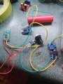
So im useing an RCWL-0516 microwave sensor.
I have it powered from an 18650 battery thats connected to a balance/charge board. this supplies the sensor with a measured 4.17v.
the output voltage from the sensor is 3.3volts when triggered. one time movement gives a 2 second open gate at 3.3v, constant movement makes it a repeatable trigger, so always on. i need it to power a 6v minimum geared motor.
My thought was to place a dc 2-24v to 5-28v step up boost converter module to take it up to 6v at the geared motor when the sensor is activated.
this does not seem to work, or im doing something wrong. im using the ground from the out circuit from the charge board, the live is from the out of the sensor, so when movement happens, in theory the gate should open, supplying 3.3v to the step up board, which is boosted to 6v. when movent triggers the sensor, its only pushing out .33v. if i remove the out wire to the charge board, it shows 3.3v

How can i get 6v to the motor from this sensor?

I also have the same issue when using this sensor to a 5v laser..not enough power getting to it.

Any help is appreciated..
Thanks guys

Roy
 
Last edited:

AlbertHall

Joined Jun 4, 2014
12,344
It sounds like the sensor output will supply only a limited current. This is to be expected. You should use the sensor output to control a separate power source for the motor, perhaps via a logic level MOSFET. Something like this:
1592068265336.png
 

Thread Starter

Royincanada

Joined Jun 13, 2020
14
Hey Albert.
This sounds about right. Again, things like this are above what I know at this point, all part of my learning curve.
What kind of component would this be?
 

Thread Starter

Royincanada

Joined Jun 13, 2020
14
I have a few mosfets here, which one would work best in you guys opinion and whats the D1?
Still learning about these..
Thanks guys:)
 

AlbertHall

Joined Jun 4, 2014
12,344
I can't say which of the ones you have would be best as I don't know what you have.
As motors are inductive they generate a, possibly large, voltage when they are turned off. There may be enough voltage to damage the MOSFET and the diode kills that voltage.
 

Thread Starter

Royincanada

Joined Jun 13, 2020
14
oh, ok, that makes sense.
its a very small like TINY 6v geared motor.
I have available these.
IRF740
IRF610

Would either of these work Albert?
 
Lets take a look at the IRF740; https://www.vishay.com/docs/91054/91054.pdf

Vgs (threshold) is between 2 and 4 volts. This is the point where the FET STARTS to turn on. In figure 3, you will see it's fully on at 7.5V.

then:

Drain-Source On-State Resistance RDS(on) VGS = 10 V ID = 6.0 A Rds(on)=0.55Ω

Then RDS(on) starts to matter. So, you can typically get 6A of drain current at 10V

The datasheet also tells you that Vgs can see +-20V without blowing up.

I'm looking at the one parameter you need, a very low Vgs is not there.

Usually you put a 100 ohm resistor in series with the gate and a big resistor from the gate to ground. The former helps deal with capacitance of the gate. The latter bleeds of the leakage current. This is a simple driver.
 

Thread Starter

Royincanada

Joined Jun 13, 2020
14
Thanks for that.
So, id need to use the 740 with a 100 ohm resistor, yes?
so it would be v-out from sensor to 100 ohm resistor to the pin1 740? pin 2 goes to the ground terminal of motor, pin 3 goes to ground of supply.. this is right?
Sorry for limited knowledge, still very much learning about mosfets
thanks
Roy
 

Thread Starter

Royincanada

Joined Jun 13, 2020
14
So here is the initial layout using the irf740
Battery goes to a charge board that supplies 4.7v
From charge board grounds goes to ground on sensor, live goes via switch to live on sensor.
Ground on sensor also goes to source pin 3 on mosfet.
V-out trigger on sensor (middle) goes to gate pin 1 on mosfet.
Drain pin 2 mosfet goes to ground in on step up board.
Switch also goes to v-in on step up board, from there it goes to motor.
Where am I getting this wrong guys?
 

Attachments

Thread Starter

Royincanada

Joined Jun 13, 2020
14
Could you recommend a mosfet I could use?
I am s still very rookie with these and don't want to get wrong type.
Thanks
Roy
 

Thread Starter

Royincanada

Joined Jun 13, 2020
14
the data sheet says 5v.
so if i read the Data Sheet correctly, as per figure 3 its fully on at 3v?
the sensor v-out sends 3.3v at activation, so the IRL540 would work for what i need, if im reading this right.

Just need clarification on minimum so i can also learn from this about mosfets.

Thank you all so so much for the assistance, you have saved me so many hours and will be visiting here frequently hoping that i can also help others with the experiences ive had.
Thank you guys.
Roy
 
Last edited:

Thread Starter

Royincanada

Joined Jun 13, 2020
14
Great, this makes sense to me now.
More stuff I've learned
Thank you guys, so very much.
I'll get the fet in and report back..

Thanks again guys.
Roy
 
In my sample datasheet, there is a gate source leakage of +-100 nA. You have to provide a place for that current to go, so you might find a 10K to 100K resistor to ground at the gate. That's a tradeoff between reliability, power consumption and cost. Cost being, use a resistor that you use a lot of.

All devices are not "ideal", and this would be a parasitic. Without the resistor, the FET would turn on when not connected to anything. The 100 ohms is to isolate the gate capacitance. A "rule" is that the voltage across a capacitor cannot change instantaneously is what your trying to fix.

The corrolary is that the current through an inductor cannot change instantaneously. This is why there is a surge current when inductors such as motors are first turned on. The winding resistance dominates.
 
Last edited:

Thread Starter

Royincanada

Joined Jun 13, 2020
14
Ok, I remember you saying about this before.
Will be adding a resistor also, avoid false triggers and maintain a bit more battery life.
Thank you so so so much for your help.
Roy
 
Top