Well, I used a screwdriver to dig at it until I saw the bare PCB under the green. That turned my output voltage to 1.77v.
Ah well, just happy they are cheap. I guess I could send an email to the company and ask them to give me a picture of how it's supposed to look after cutting.
Ah ok, I'll try actually cutting all the way through it with a utility knife.
I assume it would, but I don't have the tool to turn it. I stuck my little screwdriver in it and twisted but nothing changes. I put a 9v on it and am getting a steady 8.76V out of it.
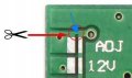
I'm about to try cutting it as the picture shows, I made a 5v solder bridge so I'm hoping I don't cut or break too much.
"The use of scissors to indicate “cut” is very misleading. The instruction means to cut he PCB trace. " - assuming I can tell which line is the trace I think it will work. I soldered the 5v bridge so if I mess up anything higher than that I don't really care.
With the power of the internet, I'll let you know how it goes on the next line...
Well, the scissors image does not mean use actual scissors. I'll have to figure out how to scratch the area to cut the trace maybe.
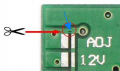
I wish they used like a different color to draw a line to show exactly what you're supposed to cut. It looks like I'm supposed to cut just a little bit of trace coming off the top of the solder bridge spot for.
Do you have a load on the regulator? Some voltage regulators will not adjust or regulate properly without a load. Try it with an LED on the output (make sure you add the proper resistor).
No? I mean the second image was to show my attempt with a screwdriver just digging at it.
But now I'm just getting more and more confused. I don't see a "bridge" I see a light green area that the blue arrow points to, then under that a dark green line that goes up and down, and the dark green line goes just above the top port. I am thinking that little overreach by the dark green line is the bridge that needs to be cut like in my photoshopped image.
I don't know what the enable port does so I left it alone. From what I read, but didn't grasp, it has something to do with keeping one of the other pins high.
Hmm, no I didn't try with a load. but I will pull it out of the garbage and check, but if I did a good job on cutting the "bridge" I think it would be ok because it was showing 8.7v from my 9v battery before my screwdriver modification.
Do you have a load on the regulator? Some voltage regulators will not adjust or regulate properly without a load. Try it with an LED on the output (make sure you add the proper resistor).
I tried that, maybe my screwdriver was too big or too small to catch to turn it I guess, but that looks like a Phillips head screwdriver should adjust it. Or maybe I just didn't spin it in the right direction enough.
Maybe I'll just do that on the next one. 2 down, 3 to go - pack of 5.
Nevermind I see it now - In the original phone on Amazon, they do show an example of what it looks like after the bridge is cut. Now that I see what I'm supposed to cut, I'll try in the morning.

 Facebook
 Google
 GitHub
 Linkedin






![DROK 5pcs Mini Voltage Reducer DC 4 5-24V 12V 24V Step Down to 5V Buck Conve[...].png](https://forum.allaboutcircuits.com/data/attachments/159/159986-6bd141393ee30342b8cfe8b1ea00218b.jpg "DROK 5pcs Mini Voltage Reducer DC 4 5-24V 12V 24V Step Down to 5V Buck Conve[...].png")