Microcontroller PIC16F690 ADC to DAC problem

Thread Starter

ArakelTheDragon

Joined Nov 18, 2016
1,366
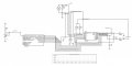
I am making a circuit with PIC16F690, but I get a wrong result on the output.
When I have 1.21 volts on the ADC, I get 2.94V on the DAC output. If I lower the ADC input, the DAC output gets higher, if I increase the ADC input, the DAC output gets lower, any ideas?

I am using the CCS PIC C compiler, v5.61.
Code:
/* Main.c file generated by New Project wizard
 *
 * Created:   Sun Jul 2 2017
 * Processor: PIC16F690
 * Compiler:  CCS for PIC
 */

#include <16F690.h>
#include <math.h.>
#fuses NOMCLR, NOPROTECT, NOWDT, INTRC_IO
#use delay (clock=4M)

                                        /* Prototypes */           
void Initialization ();

int main (void)
 { 
                                        /* Local variables */
   unsigned int8 i = 0;
   int8 ADC_sample = 0;
     
                                        /* Initiazlization */
   Initialization ();
     
   while (1)
   {
     for (i=0; i<256; ++i)
     {
         delay_ms (100);
         ADC_sample = read_adc ();                            /* Read ADC on pin RA0 */
         output_c (~ADC_sample);
     }
   }
   return 0;
 }

                                        /* Functions */
void Initialization ()
{
                                                    /* Setup ADC module and pins (channels) */
    setup_adc (ADC_CLOCK_INTERNAL);
    setup_adc_ports (sAN0);
    set_adc_channel (0);
   
                                                    /* Setup comparator */
    setup_comparator (NC_NC_NC_NC);
                                                    /* Setup CVref */
    setup_vref (FALSE);
}
 

Attachments

MrChips

Joined Oct 2, 2009
34,809
ADC has a given conversion factor, i.e. volts to digital value.
DAC has a given conversion factor, i.e. digital value to volts.

Don't assume that the conversion factor for the ADC is the same as for the DAC.
 

Thread Starter

ArakelTheDragon

Joined Nov 18, 2016
1,366
The ADC is 8 bit, the DAC is 8 bit, even if the ADC was 10, that should not make a difference so much.

ADC range from 0 to 5V (from 0 to 255)
DAC range from -5 to +5V (from -128 to 127)
 

ericgibbs

Joined Jan 29, 2010
21,439
hi A,
Your circuit is showing the Bit pattern reversed on the circuit connections.???
If so, this would reverse the sense of the DAC signal.

Eric
 

Attachments

Thread Starter

ArakelTheDragon

Joined Nov 18, 2016
1,366
My circuit is showing 5V output on 0.6V input and on 1V input its showing 2.9V output. When the input rises, the output falls and the opposite.
 

ericgibbs

Joined Jan 29, 2010
21,439
hi,
I have re-checked the DAC0800 PDF and they are showing B1 as MSB, which is in line with your drawing.:(

Can you check the bit pattern output on the 16F690 for a known ADC input voltage, lets know what you measure.
E
 

Thread Starter

ArakelTheDragon

Joined Nov 18, 2016
1,366
Its not showing it reversed, despite that it looks so for the DAC, the datasheet says that B1 is the bit connected to RC7 and B8 is connected to RC0.
 

MrChips

Joined Oct 2, 2009
34,809
If you have the DAC800 wired as for Basic Unipolar Negative Operation then try reversing the connection to your meter display.

DAC0800.jpg
 

Thread Starter

ArakelTheDragon

Joined Nov 18, 2016
1,366
MSB means most significant bit and LSB is least significant bit, that means MSB is RC7 and LST is RC0?

When I output the values from 0 to 255 from a simple counter, everything is OK, that means that the problem is elsewhere? Perhaps in the setup of the ADC?
 

ericgibbs

Joined Jan 29, 2010
21,439
hi A,
CCS is not my programming language, but I found this definition.
The ~ operator is bitwise NOT, it inverts the bits in a binary number:
Try deleting the tilde ~ on the output_c (~ADC_sample);

E
 

MrChips

Joined Oct 2, 2009
34,809
negative x does not make x a negative number if x is an unsigned 8-bit integer.

If you want to reverse x use

x = 255 - x

Edit: make ADC_sample and unsigned 8-bit integer

Watch out for conversion from 10-bit to 8-bit integers.
 

Thread Starter

ArakelTheDragon

Joined Nov 18, 2016
1,366
I tried both options, it does not work, when I output a value from 0 to 255 I get from -5 to +5 on the DAC output, but when I output the value from the ADC something is wrong. I cant understand why because even if the binary value was not allright it still wouldnt go up when the ADC goes down. I will try reversing it and see what will happen.

The ADC should be represented like this:
5/256 = 0.02
This means for 1V on the ADC we have 1/0.02 = 50
We output 50 (0b00110010) to dac and it should give 2V
But there is no sense why the when the ADC goes up, the DAC goes down.
 

MrChips

Joined Oct 2, 2009
34,809
I tried both options, it does not work, when I output a value from 0 to 255 I get from -5 to +5 on the DAC output, but when I output the value from the ADC something is wrong. I cant understand why because even if the binary value was not allright it still wouldnt go up when the ADC goes down. I will try reversing it and see what will happen.

The ADC should be represented like this:
5/256 = 0.02
This means for 1V on the ADC we have 1/0.02 = 50
We output 50 (0b00110010) to dac and it should give 2V
But there is no sense why the when the ADC goes up, the DAC goes down.
Then you need a way of monitoring the bits you receive from the ADC. Do you have a debug mode on your IDE?
 
Top