Facebook
 Google
 GitHub
 Linkedin
Hello all,
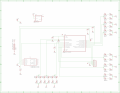
I am trying to program a Microchip and all connections seem to be connected correctly. I have a 4.7KOhm resistor to pull up MCLR, VPP, VSS, as well as PGC and PGD connected. There is also a 1Uf cap connected between VPP and Ground. When programming I recieve the message
"Device ID Revision = 00000007
Programming...
The following memory regions failed to program correctly:
Program Memory
Address: 00000000 Expected Value: 000000a5 Received Value: 000000ff
Programming failed"
My code is as follows, This builds with no errors or warnings but just does not program, The PIC is a Pic18F1320 and I get the same message regardless of being powered from 3V from the circuit or 5V from the pickit3 express.
<code>
#include <p18f1320.h>
#include <usart.h>
#include <delays.h>
#include <stdlib.h>
#include <adc.h>
//PROTOTYPES
void serial(void);
void openusart(void);
void oscillator(void);
char * itoa( int value, char * string );
void OpenUSART( unsigned char config,
unsigned int spbrg);
void openadc(void);
void ConvertADC( void );
char BusyADC( void );
int ReadADC( void );
//PROTOTYPES
//Configuration bits--------------------
#pragma config OSC = INTIO2, FSCM = OFF
#pragma config PWRT = OFF, BOR = OFF
#pragma config WDT = OFF
#pragma config MCLRE = OFF
#pragma config STVR = OFF, LVP = OFF, DEBUG = OFF
#pragma config CP0 = OFF, CP1 = OFF
#pragma config CPB = OFF, CPD = OFF
#pragma config WRT0 = OFF, WRT1 = OFF
#pragma config WRTB = OFF, WRTC = OFF, WRTD = OFF
#pragma config EBTR0 = OFF, EBTR1 = OFF
#pragma config EBTRB = OFF
//End Configuration bits----------------
void openusart(){
// Start configuration of USART
OpenUSART( USART_TX_INT_OFF & //CONFIGURE USART
USART_RX_INT_OFF &
USART_ASYNCH_MODE &
USART_EIGHT_BIT &
USART_CONT_RX &
USART_BRGH_HIGH, 8);
// End configuration of Usart
ADCON1bits.PCFG5 = 1;
ADCON1bits.PCFG6 = 1;
}
void openadc(){
ADCON1=0b01100011;
ADCON2=0b10001001;
}
void oscillator(){
OSCCON = 0b01110000;
}
//variable definitions
char time[8];
char printresulty[8];
char printresultx[8];
char printresultz[8];
int resulty;
int resultx;
int resultz;
//end variable definitions
//START MAIN CODE-----------------------
void main(){
oscillator(); // call oscillator config
openusart(); // call usart config
openadc(); // call adc config
while(1){
//ADConversion start
ADCON0=0b00010001;
Delay10TCYx(4);
ConvertADC();
while( BusyADC() );
resulty = ReadADC();
//ADConversion end
//ADConversion start
ADCON0=0b00001101;
Delay10TCYx(4);
ConvertADC();
while( BusyADC() );
resultx = ReadADC();
//ADConversion end
//ADConversion start
ADCON0=0b00001001;
Delay10TCYx(4);
ConvertADC();
while( BusyADC() );
resultz = ReadADC();
//ADConversion end
//Convert values to something I can display in Hyperterminal
itoa (resulty,printresulty);
itoa (resultx,printresultx);
itoa (resultz,printresultz);
//end Convert values to something I can display in Hyperterminal
//Start Spitting out data in Hyperterminal
putrsUSART((const rom far char *)"Y = ");
putsUSART(printresulty);
putrsUSART((const rom far char *)", X = ");
putsUSART(printresultx);
putrsUSART((const rom far char *)", Z = ");
putsUSART(printresultz);
putrsUSART((const rom far char *)"\n\r");
Delay10KTCYx(10);
//End Spitting out data in Hyperterminal
}
//End MAIN CODE
}
</code>
Thanks so much, I have build several tries and all recieve this same message so hopefully its something in the code or something I am doing wrong.
I am trying to program a Microchip and all connections seem to be connected correctly. I have a 4.7KOhm resistor to pull up MCLR, VPP, VSS, as well as PGC and PGD connected. There is also a 1Uf cap connected between VPP and Ground. When programming I recieve the message
"Device ID Revision = 00000007
Programming...
The following memory regions failed to program correctly:
Program Memory
Address: 00000000 Expected Value: 000000a5 Received Value: 000000ff
Programming failed"
My code is as follows, This builds with no errors or warnings but just does not program, The PIC is a Pic18F1320 and I get the same message regardless of being powered from 3V from the circuit or 5V from the pickit3 express.
<code>
#include <p18f1320.h>
#include <usart.h>
#include <delays.h>
#include <stdlib.h>
#include <adc.h>
//PROTOTYPES
void serial(void);
void openusart(void);
void oscillator(void);
char * itoa( int value, char * string );
void OpenUSART( unsigned char config,
unsigned int spbrg);
void openadc(void);
void ConvertADC( void );
char BusyADC( void );
int ReadADC( void );
//PROTOTYPES
//Configuration bits--------------------
#pragma config OSC = INTIO2, FSCM = OFF
#pragma config PWRT = OFF, BOR = OFF
#pragma config WDT = OFF
#pragma config MCLRE = OFF
#pragma config STVR = OFF, LVP = OFF, DEBUG = OFF
#pragma config CP0 = OFF, CP1 = OFF
#pragma config CPB = OFF, CPD = OFF
#pragma config WRT0 = OFF, WRT1 = OFF
#pragma config WRTB = OFF, WRTC = OFF, WRTD = OFF
#pragma config EBTR0 = OFF, EBTR1 = OFF
#pragma config EBTRB = OFF
//End Configuration bits----------------
void openusart(){
// Start configuration of USART
OpenUSART( USART_TX_INT_OFF & //CONFIGURE USART
USART_RX_INT_OFF &
USART_ASYNCH_MODE &
USART_EIGHT_BIT &
USART_CONT_RX &
USART_BRGH_HIGH, 8);
// End configuration of Usart
ADCON1bits.PCFG5 = 1;
ADCON1bits.PCFG6 = 1;
}
void openadc(){
ADCON1=0b01100011;
ADCON2=0b10001001;
}
void oscillator(){
OSCCON = 0b01110000;
}
//variable definitions
char time[8];
char printresulty[8];
char printresultx[8];
char printresultz[8];
int resulty;
int resultx;
int resultz;
//end variable definitions
//START MAIN CODE-----------------------
void main(){
oscillator(); // call oscillator config
openusart(); // call usart config
openadc(); // call adc config
while(1){
//ADConversion start
ADCON0=0b00010001;
Delay10TCYx(4);
ConvertADC();
while( BusyADC() );
resulty = ReadADC();
//ADConversion end
//ADConversion start
ADCON0=0b00001101;
Delay10TCYx(4);
ConvertADC();
while( BusyADC() );
resultx = ReadADC();
//ADConversion end
//ADConversion start
ADCON0=0b00001001;
Delay10TCYx(4);
ConvertADC();
while( BusyADC() );
resultz = ReadADC();
//ADConversion end
//Convert values to something I can display in Hyperterminal
itoa (resulty,printresulty);
itoa (resultx,printresultx);
itoa (resultz,printresultz);
//end Convert values to something I can display in Hyperterminal
//Start Spitting out data in Hyperterminal
putrsUSART((const rom far char *)"Y = ");
putsUSART(printresulty);
putrsUSART((const rom far char *)", X = ");
putsUSART(printresultx);
putrsUSART((const rom far char *)", Z = ");
putsUSART(printresultz);
putrsUSART((const rom far char *)"\n\r");
Delay10KTCYx(10);
//End Spitting out data in Hyperterminal
}
//End MAIN CODE
}
</code>
Thanks so much, I have build several tries and all recieve this same message so hopefully its something in the code or something I am doing wrong.


 The PK2 has a diagnostic mode, not sure if the PK3 offers the same thing.