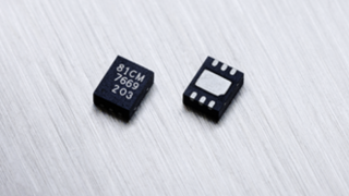
Micro Joysticks In Place Of Dial On Servo Testers

KeithWalker

Joined Jul 10, 2017
3,625

MisterBill2

Joined Jan 23, 2018
28,485
Ifthe board has plated thru holes the best chance will be to carefully snip the pins off close to the board and then remove them one at a time. If the circuit board does not have plated thru holes then use solderwick to remove the solder one at a time until the pot comes off. It will take more that one attempt to remove all of that solder.
And that photo is rather blurry and quite small in the area we need to see.
 

Thread Starter

DragonTheta

Joined Feb 6, 2022
89
Potentiometers are always the same. The center pin is the wiper and the end pins are the ends of the resistor.
Ifthe board has plated thru holes the best chance will be to carefully snip the pins off close to the board and then remove them one at a time. If the circuit board does not have plated thru holes then use solderwick to remove the solder one at a time until the pot comes off. It will take more that one attempt to remove all of that solder.
And that photo is rather blurry and quite small in the area we need to see.
Thank you

So will either the left or right pin work for the 5v or the ground?

I don't know if it has plated through holes. The pins go through to the other side. I got the solder off one with the wick so I think it will work

Thanks
 

Thread Starter

DragonTheta

Joined Feb 6, 2022
89
Thank you

I went back to the Arduino and got that to work with one motor. I couldn't get it to work with two motors so I'm going to go one motor at a time. I want to set up four of them together, powered by one lipo battery. Do I connect the plugs on the ESCs black to black and red to red, to get the one battery to power all four ESCs?
 

MisterBill2

Joined Jan 23, 2018
28,485
Red being the positive input connection to the ESC, and black being the negative, short answer is YES. All run with the same supply voltage. In addition, as I am guessing that the same black wire is also the return line for the control signal, connect the signal return line at that same point to prevent possible cross-talk of signals.
 

Thread Starter

DragonTheta

Joined Feb 6, 2022
89
Red being the positive input connection to the ESC, and black being the negative, short answer is YES. All run with the same supply voltage. In addition, as I am guessing that the same black wire is also the return line for the control signal, connect the signal return line at that same point to prevent possible cross-talk of signals.
Thank you,

When I say red and black I'm talking about the battery plug where the ESC plugs in. Is that what you're talking about?

There's another three wires. The 5v, ground, and signal for the ESC and for whatever I plug the ESC into. Normally it would be a flight controller, I think.

The first two that I'm calling red and black are the thick wires from the battery. Is that what I connect positive to positive and negative to negative?
 

MisterBill2

Joined Jan 23, 2018
28,485
Thank you,

When I say red and black I'm talking about the battery plug where the ESC plugs in. Is that what you're talking about?

There's another three wires. The 5v, ground, and signal for the ESC and for whatever I plug the ESC into. Normally it would be a flight controller, I think.

The first two that I'm calling red and black are the thick wires from the battery. Is that what I connect positive to positive and negative to negative?
[That is EXACTLY what I am telling you! All of the RC servo devices powered in parallel, and the common from the controlcircuit referenced to the same common negative side at that point.
 

Thread Starter

DragonTheta

Joined Feb 6, 2022
89
Thank you

It was working fine, but then I made a couple changes and now it's not working. I had it connected to another Arduino with the 5 volt and ground going between the two Arduinos, although the other Arduino was not connected to anything with signal. And I had it set up with the electronic speed controller soldered to the motor, and the Arduino signal soldered into the electronic speed controller, and 5 volt and ground going from the Arduino and the speed controller, and it was working fine before. Then I separated the Arduinos from each other so the 5 volt and ground were disconnected. Then it was just one Arduino. I also reconnected the ESC to a different motor. I have no reason to believe there's anything wrong with that motor, and it was working a little while before. now when I plug everything in, the ESC goes through its normal initialization startup, but then when I push the throttle, the motor stutters. When I put the throttle back to zero, the motor kept stuttering. And afterward, the capacitors on the back of the ESC were extremely hot. The motor also heated up a bit.

Do you know what I can do to get it to work?
 

Thread Starter

DragonTheta

Joined Feb 6, 2022
89
First, what 5V pin on the two Arduinos are connected together? And what pins (or sources such as USB or power jack) are used to power the Arduinos?
The Arduinos aren't connected anymore, and when they were connected it was by the pad marked 5v on the Arduinos. The Arduino is powered by a 5v wire from the ESC.
 

djsfantasi

Joined Apr 11, 2010
9,237
The Arduinos aren't connected anymore, and when they were connected it was by the pad marked 5v on the Arduinos. The Arduino is powered by a 5v wire from the ESC.
If the ESC output connects to the 5V pin on the Arduino, it’s not guaranteed to work. The 5V pin was designed to be an output. When inputting 5V there, you’re back feeding the Arduino regulator. It works (many people do it), but it can and has caused a failure.

The better way to power the Arduino is to use a 7 or 9 volt (better) ESC and connect it to the Vin pin.
 

Thread Starter

DragonTheta

Joined Feb 6, 2022
89
If the ESC output connects to the 5V pin on the Arduino, it’s not guaranteed to work. The 5V pin was designed to be an output. When inputting 5V there, you’re back feeding the Arduino regulator. It works (many people do it), but it can and has caused a failure.

The better way to power the Arduino is to use a 7 or 9 volt (better) ESC and connect it to the Vin pin.
Thank you

If I don't find any 7v or 9v ESCs, can I supply battery voltage from the lipo and pass it through a voltage reducer to get it to 9v?
 
Last edited:

djsfantasi

Joined Apr 11, 2010
9,237
Thank you

If I don't find any 7v or 9v ESCs, can I supply battery voltage from the lipo and pass it through a voltage reducer to get it to 9v?
The Arduino Vin pin can take 7-12 volts. Anything within that range will work. But 9V is a sweet spot. What voltage is your LiPo pack?

I just awoke that you’re referring to an ESC. What do you think that acronym stands for?
 

Thread Starter

DragonTheta

Joined Feb 6, 2022
89
The Arduino Vin pin can take 7-12 volts. Anything within that range will work. But 9V is a sweet spot. What voltage is your LiPo pack?

I just awoke that you’re referring to an ESC. What do you think that acronym stands for?
Thank you. I will plan to power the Arduino in that way.

The lipo is 14.8v or 4s.

ESC to me is electronic speed controller.
 

djsfantasi

Joined Apr 11, 2010
9,237
Thank you. I will plan to power the Arduino in that way.

The lipo is 14.8v or 4s.

ESC to me is electronic speed controller.
I thought so… Why are you using an ESC to provide constant power? What you need is a DC-DC converter. These come in small modules and are used to convert one DC voltage to another. They even can be used to increase voltage. I.e., change 3V to 5V.

You can also purchase a variable DC-DC converter. I.e., 14.8V to 7V easily.
 

Thread Starter

DragonTheta

Joined Feb 6, 2022
89
I thought so… Why are you using an ESC to provide constant power? What you need is a DC-DC converter. These come in small modules and are used to convert one DC voltage to another. They even can be used to increase voltage. I.e., change 3V to 5V.

You can also purchase a variable DC-DC converter. I.e., 14.8V to 7V easily.
Ok, I think that's what I bought.

10 Pieces 5v Regulator Module Mini Voltage Reducer DC 4.5-24V 12V 24V to 5V 3A Volt Buck Converter Power Supply Transformer Module https://a.co/d/hjILXnq
 
Top