Facebook
 Google
 GitHub
 Linkedin

thatoneguy
- Joined Feb 19, 2009
- 6,359
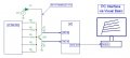
I just read an article on this. Analog + Digital If you decided to build a uC based tracer that emulated the real tracers, but less precise, a small screen could give you a good idea of what is going on for a trace set. I'm thinking basic basic: 10 bit DAC and ADC, not analog quality.
Article suggested a 150VDC supply, then run that through a 1MΩ resistor at the top of a voltage divider for the current source, Then switched 1% metal film resistors in 2 ranges for coarse and fine for uA to mA base drive.
The reasoning was a 1% error on the resistor wouldn't be much of an error at all after calibration, where using lower voltages would not be nearly as stable (1% of 10V is a lot more than 1% of 150V). Knowing the exact uA to mA base current is a difficult task, as measuring that low it will change it, not to mention the noise floor.
Calibrating a grid for the screen would be a bit of a task, but the pixels are known for dimensions, giving a starting point. It could be drawn by the uC itself. Maybe a bit jaggy, but drawn.
Just a jumble of ideas tossed out. I'll be interested to see how this develops.
Article suggested a 150VDC supply, then run that through a 1MΩ resistor at the top of a voltage divider for the current source, Then switched 1% metal film resistors in 2 ranges for coarse and fine for uA to mA base drive.
The reasoning was a 1% error on the resistor wouldn't be much of an error at all after calibration, where using lower voltages would not be nearly as stable (1% of 10V is a lot more than 1% of 150V). Knowing the exact uA to mA base current is a difficult task, as measuring that low it will change it, not to mention the noise floor.
Calibrating a grid for the screen would be a bit of a task, but the pixels are known for dimensions, giving a starting point. It could be drawn by the uC itself. Maybe a bit jaggy, but drawn.
Just a jumble of ideas tossed out. I'll be interested to see how this develops.