Method of Voltage measurement

Thread Starter

hunterage2000

Joined May 2, 2010
487
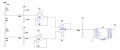
I'm trying to build a PC multimeter and from the limited knowledge I know about how a multimeter processes an input from 2 probes to the adc stage. I have come up with.

1). The multimeter can measure up to 100V so:
each probe input goes to a voltage scaling circuit that outputs 0V for an input of -50V and 12V for +50V
2). These outputs are buffered from +-15 dual supply 741's and go to a +-15 dual supply differential amplifier (AMP03)

3). The difference between the 2 probe inputs at the output of the +-15 dual supply differential amplifier (AMP03).

4). The +-15 dual supply differential amplifier (AMP03) output goes to another voltage scaling circuit that outputs 0V for an input of -12V and 5 for an input of 12V.

5) This 0V to 5V output is the input to a pic adc.

I can't really get around the initial stage where the 2 input probes determine the polarity of the measurement.
 

ebeowulf17

Joined Aug 12, 2014
3,307
I can't really get around the initial stage where the 2 input probes determine the polarity of the measurement.
No determination of polarity happens at an early stage. You need to stop thinking in those terms.

I think you've made your process more complicated than it needs to be (more scaling stages and op amps than are really necessary,) but I don't know the exact method any meter uses, so I'm not sure exactly what I would eliminate.

Sticking with your proposed work flow for now, polarity is only determined after you've done ALL of those scaling, amplifying, and shifting steps, and AFTER you've done your ADC step. The output of the ADC will be a positive number. It will fall within a range whose size is determined by your ADC (10 bit = 0-1023, 16 bit = 0-65,535, etc.) An ADC output of 0 will represent the lowest voltage your circuit is configured to measure (-100V if your desired range is 100V measurements.) The highest possible ADC value (1023 in the 10 bit example) will represent your highest measurable voltage (+100V in this example.) Zero volts is represented by the number halfway from min to max ADC output (511 in this example.)

Neither the circuit, nor the ADC, ever determines any polarity. The code you write to read values from your PC volt meter and display them must do the basic math of scaling a range from [0-1023] to a range of [-100 to +100] The polarity is essentially the last step before physically displaying the result.
 

Thread Starter

hunterage2000

Joined May 2, 2010
487
I guess my explanation didn't help much?
Well, it kind of did. I have a 0 to 5V adc voltage which represents a measurement of -50V to +50V but I can't really get my head around how a multimeter measures a voltage with no polarity and determines its polarity at the end.

The attached for example shows a voltage divider where the drop over IN+ and IN- can either be 3.3V or -3.3V depending on the probes.

Can anyone explain what I am not seeing?
 

Attachments

MrChips

Joined Oct 2, 2009
34,866
We are going around in circles.

Your ADC measures a voltage in the range 0 to 5VDC and converts it to a number. Let us say, for example, the number range is 0 to 1023.

The job of the input circuitry is to shift all voltages upwards so that there are no negative voltages.
Thus we add 2.5V to the input voltage. Now our input range of -2.5V to +2.5V gets shifted to 0 to 5V which the ADC can read as 0 to 1023.
-2.5V is read as 0.
0V is read as 512.
+2.5V is read as 1023.

When the digital processor sees a reading between 0 and 511 it knows this is a negative input and displays the results accordingly.
 

Thread Starter

hunterage2000

Joined May 2, 2010
487
Isnt this similar to what I'm doing? The max measured voltage is 100V so I've scaled the -50V to +50V range to 0 to 12V for the buffers and differential amplifier then the -12V to +12V range to 0 to 5V for the adc.
 

MrChips

Joined Oct 2, 2009
34,866
Isnt this similar to what I'm doing? The max measured voltage is 100V so I've scaled the -50V to +50V range to 0 to 12V for the buffers and differential amplifier then the -12V to +12V range to 0 to 5V for the adc.
You tell me. I have no idea what you are doing.
You asked how a voltmeter reads both negative and positive voltages.
 

Thread Starter

hunterage2000

Joined May 2, 2010
487
You tell me. I have no idea what you are doing.
You asked how a voltmeter reads both negative and positive voltages.
Yeah should really state what I'm doing. The attached is the circuit of my voltmeter.

Basically the 2 probe inputs are scaled down to 0 -12V, buffered then the difference is subtracted with a differential amplifier.

The output is scaled down to 0V - 5V and read by the adc. 0V shows a measurement of -50 and 5 shows a measurement of +50V with everything inbetween.

I'm guessing a DVM measures the drop between the probes in a better and more practical way?
 

Attachments

MrChips

Joined Oct 2, 2009
34,866
There are multiple problems with your approach.
You are still thinking about independent probes A and B.

Don't level shift the inputs. Remove the 2.4MΩ pullup resistors.
Don't use 741 opamps. Use the IN-amp or look at the data sheet for examples on a 3-amp instrumentation amplifier.

INA105 Precision Unity Gain Differential Amplifier


What you need is an instrumentation amplifier operating from dual power supply.
Then you shift the output of the IN-amp with another amplifier to give the 0-5V range.
 
Top