Facebook
 Google
 GitHub
 Linkedin
Hi, everybody!!!
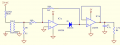
I am trying to measure small mains current. My loads are between 6-12 W up to about 600 W. I tried with Hall effect based ICs but they appeared to be quite noisy and not suitable for such small loads. Then decided to go with CT. Now I took CT 500:1, with burden 330 Ohm and op amp (so called precision rectifier) for buffering and rectifying my signal. With this setup I can achieve almost linear output 70mA -> ~70mV and 440mA -> ~500mV - measured with non RMS multimeter.
My intend is that this output voltage would be measured by MCU.
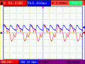
Because the shape of the rectified sin, didn't appear to be good? , I placed 4,7uF cap at the output. Is it worth filtering the input of the op amp (the secondary of CT)? Or is it possible to use bridge rectifier instead of op amp precision rectifier (having in mind the voltage drops over each diode)?
Thanks very much for help!!!!
I am trying to measure small mains current. My loads are between 6-12 W up to about 600 W. I tried with Hall effect based ICs but they appeared to be quite noisy and not suitable for such small loads. Then decided to go with CT. Now I took CT 500:1, with burden 330 Ohm and op amp (so called precision rectifier) for buffering and rectifying my signal. With this setup I can achieve almost linear output 70mA -> ~70mV and 440mA -> ~500mV - measured with non RMS multimeter.
My intend is that this output voltage would be measured by MCU.
Because the shape of the rectified sin, didn't appear to be good? , I placed 4,7uF cap at the output. Is it worth filtering the input of the op amp (the secondary of CT)? Or is it possible to use bridge rectifier instead of op amp precision rectifier (having in mind the voltage drops over each diode)?
Thanks very much for help!!!!
Attachments
-
 6.8 KB Views: 33