 Facebook
 Google
 GitHub
 Linkedin
Having never had occasion to use a mechanical timer, I purchased two cheap Chinese versions, to use in powering aquarium pumps that I hope to operate in relay, with one pump on while the other toggles off, over the duration of four hours at a time, whereby each of the two pumps runs four hours on, and four hours off, to allow a rest period for each pump, while the other works in turn.
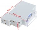
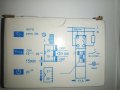
Of the two timers, the narrower width version, depicted in the attached picture labelled "Mechanical Timer Settings Window", was shipped with no written instructions, save for the connection diagram printed on the box, as shown in the attached image labelled "Narrow Width Timer Pinouts". Right away I noticed that the written labeling on the timer connection diagram shown here, had to be held upside down, in order to match the position of the connection terminals on the device, which I found perplexing, especially since no written directions were supplied with the device.
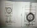
The second timer with a clock face, shown in the attached photographs labelled "Mechanical Timer Pinouts", and "Mechanical Timer Pinouts 2", proved equally baffling to connect up, such that my digital volt meter couldn't even measure the mains input voltage at the designated live and neutral input pins, when I turned on the power. The meter went into a strange error state, yet was not defective at all, since it accurately measured the 220 Volt AC mains at the wall.
The actual timer settings on both of these devices proved relatively easy to follow despite being described in somewhat cryptic terms, but I never got to test either of these timers after several utterly exasperating hours trying to guess at the meaning of explanations offered in Youtube videos posted about the convoluted and varied wiring connections for both these devices, that were ALL narrated in languages that I could not even identify. Extensive searches of Youtube's archives failed to uncover one solitary video about these two specific devices, that was narrated in the English language.
As a final recourse, I decided to pose my questions here in this forum, in the hopes that those far more versed in these matters, might be able to offer some insight into the wiring connection protocol that will enable me to use these devices as intended, without frying them due to wrong connections made in the total absence of any clear instructions for either timer variant.
Thanks in advance for any pointers that can be offered, as I finally reached my wits over several hours of flailing about and going in circles, essentially guessing at the intended meaning of the disorienting connection diagrams provided by the manufacturers, and the unintelligible foreign languages used to explain their connection and operation, in the numerous Youtube videos I sat through in bewilderment.
After considerable time spent reconnecting these two timers, while muttering to myself, I finally got them both running and keeping time, but thus far I haven't been able to see any output voltage on either one of them, so I will tinker on in the hopes of stumbling on success. The neutral line connections appear to be the ones that have thus far remained rather difficult to understand from the schematics, so I'll see how it goes.
Of the two timers, the narrower width version, depicted in the attached picture labelled "Mechanical Timer Settings Window", was shipped with no written instructions, save for the connection diagram printed on the box, as shown in the attached image labelled "Narrow Width Timer Pinouts". Right away I noticed that the written labeling on the timer connection diagram shown here, had to be held upside down, in order to match the position of the connection terminals on the device, which I found perplexing, especially since no written directions were supplied with the device.
The second timer with a clock face, shown in the attached photographs labelled "Mechanical Timer Pinouts", and "Mechanical Timer Pinouts 2", proved equally baffling to connect up, such that my digital volt meter couldn't even measure the mains input voltage at the designated live and neutral input pins, when I turned on the power. The meter went into a strange error state, yet was not defective at all, since it accurately measured the 220 Volt AC mains at the wall.
The actual timer settings on both of these devices proved relatively easy to follow despite being described in somewhat cryptic terms, but I never got to test either of these timers after several utterly exasperating hours trying to guess at the meaning of explanations offered in Youtube videos posted about the convoluted and varied wiring connections for both these devices, that were ALL narrated in languages that I could not even identify. Extensive searches of Youtube's archives failed to uncover one solitary video about these two specific devices, that was narrated in the English language.
As a final recourse, I decided to pose my questions here in this forum, in the hopes that those far more versed in these matters, might be able to offer some insight into the wiring connection protocol that will enable me to use these devices as intended, without frying them due to wrong connections made in the total absence of any clear instructions for either timer variant.
Thanks in advance for any pointers that can be offered, as I finally reached my wits over several hours of flailing about and going in circles, essentially guessing at the intended meaning of the disorienting connection diagrams provided by the manufacturers, and the unintelligible foreign languages used to explain their connection and operation, in the numerous Youtube videos I sat through in bewilderment.
After considerable time spent reconnecting these two timers, while muttering to myself, I finally got them both running and keeping time, but thus far I haven't been able to see any output voltage on either one of them, so I will tinker on in the hopes of stumbling on success. The neutral line connections appear to be the ones that have thus far remained rather difficult to understand from the schematics, so I'll see how it goes.
Attachments
-
 30.6 KB Views: 9
 -
 4.9 MB Views: 8
 -
 503 KB Views: 8
 -
 13.8 KB Views: 8
 -
 4.5 MB Views: 8


