 Facebook
 Google
 GitHub
 Linkedin
Hello All,
I am trying to design a controller which can measures voltage difference between Neutral and Ground. Very low information I found on Google and on AAC regarding this topic.
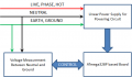
Here is my situation. I have Three wires, Live(L), Neutral(N) and Ground(G), as supply for controller. Circuit will get Power from Live and Neutral. It has ATmega328P Chip operating at 5VDC, 8MHz. I need to measure RMS value of potentiate difference between N and G. I have constrain for ATmega328P Chip but free to use any other supporting ICs like ADC etc.
N will surely have AC behavior with respect to G in unbalanced conditions. I can measure AC Signal's RMS value using ATmega328P's Single ended ADC OR External Differential ADC after necessary conditioning. I need more help in Signal Conditioning and Protection. My expected Input Voltage Difference between N and G is +-10VAC MAX.
Please give me some hints, Ideas or reference designs (If possible) before I decide which path to go for prototyping.
Thanks to ALL. Please do ask for any Query.

I am trying to design a controller which can measures voltage difference between Neutral and Ground. Very low information I found on Google and on AAC regarding this topic.
Here is my situation. I have Three wires, Live(L), Neutral(N) and Ground(G), as supply for controller. Circuit will get Power from Live and Neutral. It has ATmega328P Chip operating at 5VDC, 8MHz. I need to measure RMS value of potentiate difference between N and G. I have constrain for ATmega328P Chip but free to use any other supporting ICs like ADC etc.
N will surely have AC behavior with respect to G in unbalanced conditions. I can measure AC Signal's RMS value using ATmega328P's Single ended ADC OR External Differential ADC after necessary conditioning. I need more help in Signal Conditioning and Protection. My expected Input Voltage Difference between N and G is +-10VAC MAX.
Please give me some hints, Ideas or reference designs (If possible) before I decide which path to go for prototyping.
Thanks to ALL. Please do ask for any Query.
Attachments
-
 16.6 KB Views: 4


