 Facebook
 Google
 GitHub
 Linkedin
Hello,
I've looked at similar threads but I can't get the numerical answer I'm looking for.
I'm going through the art of electronics and student manual myself, I'm at lab#4 (transistors) 4-2 input/output impedance of the emitter follower.
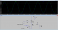
I'm simulating this circuit in LTspice (see attachment).
To determine input impedance, I have the 10k resistor and am measuring the voltage on both sides of it.
Iin = (deltaV_Left - deltaV_Right)/10Kohm
Zin = deltaV_Right/Iin which turns out to be around 960Kohms... which seems too high, I was expecting around 3.3k*150 at most.
The input signal is a 1 V[pk-pk] 1kHz sine wave.
Am I missing something?
~For the output impedance I have a 4.7uF capacitor and a 1k resistor as the load. I measure deltaV_emitter before and after attaching the load and determine the Zout as:
Vload = Vno_load * Zload/(Zload+Zout); but I get Zout ~ 1ohm which seems way too low...
Some tips would be greatly appreciated.
Thank you
I've looked at similar threads but I can't get the numerical answer I'm looking for.
I'm going through the art of electronics and student manual myself, I'm at lab#4 (transistors) 4-2 input/output impedance of the emitter follower.
I'm simulating this circuit in LTspice (see attachment).
To determine input impedance, I have the 10k resistor and am measuring the voltage on both sides of it.
Iin = (deltaV_Left - deltaV_Right)/10Kohm
Zin = deltaV_Right/Iin which turns out to be around 960Kohms... which seems too high, I was expecting around 3.3k*150 at most.
The input signal is a 1 V[pk-pk] 1kHz sine wave.
Am I missing something?
~For the output impedance I have a 4.7uF capacitor and a 1k resistor as the load. I measure deltaV_emitter before and after attaching the load and determine the Zout as:
Vload = Vno_load * Zload/(Zload+Zout); but I get Zout ~ 1ohm which seems way too low...
Some tips would be greatly appreciated.
Thank you
Attachments
-
 43.6 KB Views: 41


