Measuring higher voltage differentially into a microcontroller

Thread Starter

Sidleg

Joined Aug 5, 2014
15
Hi, I would be interested in any suggestions from the experienced contributors here for a way to measure voltages higher than the voltage my microcontroller pins are rated for. Basically I need to measure the potential difference between +10V and +6.7V. The microcontroller has a +3.3V Vdd and has a maximum pin voltage of Vdd+0.3V, with a maximum pin current of 25mA.

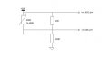
The application is measuring a temperature sensor which is essentially a thermistor whose resistance changes from 200R to 500R depending on the temperature. I have been using a voltage divider in order to get the voltage range to within what the microcontroller needs for its Vref, however I still have the problem of the voltage offset.

I am able to measure a differential input using my microcontroller, I would just like to understand better how to connect the sensor in order to do this. I'm sure there's a simple way but I haven't encountered this type of problem before and I want to make sure I have explored all the angles. Any advice very welcome!
 

crutschow

Joined Mar 14, 2008
34,285
It's not totally clear what you need. Is it to convert a voltage between 6.7V and 10v to what the micro can take.

Does the processor have an A/D converter? If so what is its input voltage range.
 

Thread Starter

Sidleg

Joined Aug 5, 2014
15
It's not totally clear what you need. Is it to convert a voltage between 6.7V and 10v to what the micro can take.

Does the processor have an A/D converter? If so what is its input voltage range.
Hi, yes it has an ADC module, with an input range of 0 to 3.3V (set as Vref).

Basically I am asking if there is some commonly used way to change the voltage from +6.7V to +10V, removing the offset which the microcontroller can't take, so that it is 0V to +3.3V instead.

@ ericgibbs - I can't modify the actual sensor so any passive components have to be connected onto nodes, in parallel effectively.

(I made a circuit diagram but I can't seem to upload it anywhere. No error details just 'there was a problem uploading your file'. I also tried uploading it to a image hosting website and this time it was definitely blocked by my work IT network, so that is probably why I can't upload it to this website either. Not for lack of trying though.)
 

ericgibbs

Joined Jan 29, 2010
18,767
(I made a circuit diagram but I can't seem to upload it anywhere. No error details just 'there was a problem uploading your file'. I also tried uploading it to a image hosting website and this time it was definitely blocked by my work IT network, so that is probably why I can't upload it to this website either. Not for lack of trying though.)
hi,
What is the file name ext type that you are trying to upload.?
Also use the 'More Options' button for easier file loading.

E
 

Thread Starter

Sidleg

Joined Aug 5, 2014
15
hi,
What is the file name ext type that you are trying to upload.?
Also use the 'More Options' button for easier file loading.

E
I tried .png & .jpg & I tried to put it on a Word page for a .docx and none of them worked. I don't think this forum allows PMs either so I can't try that. A bit frustrating as I think it would clarify things a lot!
 
Last edited:

Thread Starter

Sidleg

Joined Aug 5, 2014
15
hi Sidleg,
This circuit is one option.
LTSpice simulation.
E
Is this circuit measuring U3? The difference with my circuit is that the thermistor is not grounded, it is connected to another part of the sensor in series. It is part of a pressure sensor which compensates for temperature with the component I am trying to measure. Hence the voltage offset which is creating problems for the microcontroller pins.

I might try uploading from somewhere else to see if that makes a difference.
 
Last edited:

ErnieM

Joined Apr 24, 2011
8,377
Sidleg: you need 10 posts before you can upload files. Right now you have 6. So make some dummy posts here then upload tyour schematic.

I may have a way to do this but it depends on how and where your sensor is connected.
 

ericgibbs

Joined Jan 29, 2010
18,767
hi S,
Do as Ernie suggests, get upto 10 posts.

Where is Is this circuit measuring U3? on my circuit, Its a 10K Pot. for Zero.?:confused:

Its measuring V1 [your input] and the Vout is Vo on U1.
E
 

Thread Starter

Sidleg

Joined Aug 5, 2014
15
Sidleg: you need 10 posts before you can upload files. Right now you have 6. So make some dummy posts here then upload tyour schematic.

I may have a way to do this but it depends on how and where your sensor is connected.
Ok, finally I have it uploaded. Note that the voltage divider is additional, and not part of the actual sensor, so this part can be changed.
 

Attachments

ericgibbs

Joined Jan 29, 2010
18,767
hi Sidleg,
Do you have a stable negative voltage supply available on your project, say -10V.
If yes, there is a simpler option.
Take care you do not introduce any errors due to self heating of the Thermistor.

E
 

Attachments

Thread Starter

Sidleg

Joined Aug 5, 2014
15
Hi Eric, thanks for the reply. That's a great solution, however unfortunately I don't have a -ve voltage supply available. I do have a +3.6V supply in addition to the +10V, although the sensor will be powered by the +10V rail. Out of interest, what application do you use for the circuit modelling?
 

Thread Starter

Sidleg

Joined Aug 5, 2014
15
Thanks. So this is not such a simple problem then? I was wondering if there were a commonly used approach that maybe I just hadn't come across yet, but I suspect it is not so easy. I will probably end up using an op-amp solution, I suppose, although I would prefer to stick to passive components. Does that sound right?
 

ericgibbs

Joined Jan 29, 2010
18,767
hi Sidleg,
My concern with using the 'passive' approach is causing self heating of the thermistor, which could effect the accuracy of you measurements.
You can see from this plot, the thermistor is dissipating 0.2Watt due to self heating caused by the series components.

Would you post more details of the thermistor and way its connected into the existing system, a skecth would be helpful.
E
 

Attachments

Thread Starter

Sidleg

Joined Aug 5, 2014
15
Ok, here is a diagram taken from its datasheet. All the info I can get on the thermistor is that it has a resistance range of 200...500R (which certainly agrees with measurements taken so far), and a thermal change of 4000...5000pm/K. I will be using it to monitor patterns and trends, so there is a reasonably forgiving margin for accuracy.
 

Attachments

Top