Measuring a DC voltage source via MCP3008

Thread Starter

systemlordanubis

Joined Jul 30, 2015
17
Hi All,

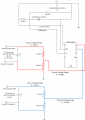
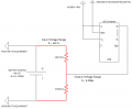
I'm currently using the MCP3008 ADC to measure some variable resistors. These resistors are connected to a 4.096v VRef and their output (as a voltage) is connected to an input of the MCP3008.

What I would like to do is find a way that I can use the MCP3008 (if possible) to measure the voltages of some other DC sources (for example; the voltage of a battery source).

The battery voltage may be up to 48v and I was first thinking of a simple voltage divider but this wouldn't work as it would be essentially a short-circuit on the battery. So I need a way to divide down the battery voltage into the range of 0-4.096v with a resolution of 0.1v (more would be great but not necessary) and to do it in a way that would be safe from short-circuit and burning out the components.

Thanks in advance
Anubis.
 

Thread Starter

systemlordanubis

Joined Jul 30, 2015
17
Hi Mcgyvr (love the pun on the name),

Thanks for the reply. Wouldn't a voltage divider cause a short circuit and burn out the resistors though (per the attached image - I'm worried the red line would act like a short-circuit)? One battery set for example is 4x 12v 150AH batteries.

Does it also matter that the ground of the batteries is separate to the ground of the ADC?

Thanks
Anubis.
 

Attachments

mcgyvr

Joined Oct 15, 2009
5,394
If there is resistance there isn't a short.. A short is no (or very..very low) resistance.. The more resistance the less current is actually flowing..
And you need to tie the ground of the ADC to the ground of the equipment so you have a common 0v reference point..

That link I posted as a bunch of good "interface" circuits for microcontrollers.. read it :)
 

#12

Joined Nov 30, 2010
18,224
You really need the first equation of electronics, Ohm's Law.
V = IR
Then figure out that a 10k ohm resistor has resistance, therefore it is not a, "short".
Really. The way you started out, it's like you're saying all circuits are shorts because they are all connected to a positive supply and the other end (negative) of the supply voltage.

Consider: 48 volts/10675 ohms = 0.0044965 amps.
How, "shorted" is that compared to a 150 amp-hour battery?
 
Last edited:

Thread Starter

systemlordanubis

Joined Jul 30, 2015
17
Hi Guys,

Thanks for the reply. I must admit, my background isn't in electronics but in computing, so I'm trying to ensure that I get the basics right before connecting something that may cause other problem. It's been many, many years since I dealt with Ohms law and of course, you're correct and I should have thought about that ;)

@mcgyvr, regarding the grounding, I can't hook the ground of the equipment to the ground of the ADC, but would this (attached) work instead?

The values of the resistors being 10K and 675Ohm would give me output voltage I'm seeking, but what sort of wattage resistors should I be using in this instance?

Thanks again for your valuable input!
Anubis.
 

Attachments

Thread Starter

systemlordanubis

Joined Jul 30, 2015
17
Hi Again,

@#12 - Based on your calculation, am I correct then in this assumption:

If 48v / 10675ohm = 0.0044965A - then 0.0044965A * 48v = 0.215832W (or 215mW)? In this case, if both resistors were 1/4w (250mW) this would be suitable? Though it is probably a good idea to get 1/2W resistors to give some extra headroom.

Thanks
Anubis.
 

CoolBeer

Joined Mar 29, 2010
40
I would personally bump the voltage divider up a bit in total resistance to keep the resistors 1/4W, it saves board space and parts cost.

Do note that the sampling capacitor in the ADC will need some current to charge, so if you make the divider too resistive it can help to buffer it with a capacitor to ground. This will also vary based on clock rate of the ADC, slower clocks and the sampling cap have a longer time to charge, but this also means less samples per unit of time, ymmv.
Do note that if you buffer it with a cap, that cap also have to charge, so if you read the ADC before that happens results will not be accurate, this also means rapid changing signals are a no-go with this approach.
 

ErnieM

Joined Apr 24, 2011
8,377
regarding the grounding, I can't hook the ground of the equipment to the ground of the ADC, but would this (attached) work instead?
The voltage in your figure you want to measure is across the 675 ohm resistor. To actually use the A/D converter to measure this voltage you need to connect to both sides of the resistor as a voltage can only exist between two points, not one.

So the ground of the battery must connect to the A/D converter as does the B input.

As far as the wattage of the resistor is concerned, if you want this to work over the long haug then derate the resistors by 50%. This means put no more that 1/2 watt into a device rated for 1 watt.
 

#12

Joined Nov 30, 2010
18,224
Hi Again,

@#12 - Based on your calculation, am I correct then in this assumption:

If 48v / 10675ohm = 0.0044965A - then 0.0044965A * 48v = 0.215832W (or 215mW)? In this case, if both resistors were 1/4w (250mW) this would be suitable? Though it is probably a good idea to get 1/2W resistors to give some extra headroom.

Thanks
Anubis.
As a matter of opinion, I use 1 ma for precision analog circuits because it is of low enough impedance to avoid most noise problems. Then I use Watt's Law and a bunch of combinations, often called the "WIRE wheel" to calculate power.

OK. You got the Watt's Law part. In this circuit the 10k resistor suffers a lot more power than the 675 ohm resistor. They both have the same amount of current because it's a series circuit, but one of them has most of the voltage. 0.0045A squared times R gives the power in each resistor.
0.2025 watts for the 10k (needs a 1/2 watt rated resistor)
0.01367 watts for the 675 ohm resistor.

Knock the current down to 1 ma by using more resistance and the power levels will go down.
 

Thread Starter

systemlordanubis

Joined Jul 30, 2015
17
Hi All,

Thanks very much for the replies.

@mcgyvr; sorry, regarding the ground, I don't know what I was thinking, you mean to have the grounds common across the circuit; I've revised the circuit diagram showing both the PSU supplying the microcontroller and ADC as well as two 'monitoring' sources. Do I have this setup (with the grounding) correct?

@#12; I've also taken your suggestion of using a higher resistance to lower the current across the monitoring circuit. In this sample I'm using a 1M Ohm resistor bringing its power down to 0.00222W and a 16.5K resistor for 0.00003679 - so in this case 1/4w resistors would be more than enough.

In the attached circuit diagram, I'm showing two battery sources that I'm wanting to monitor through the ADC (on some sites, there's actually up to 5 sources that I'll be monitoring). In this diagram I'm also showing the LM4040 4.096v voltage ref used as the reference source for the ADC. The only thing I'm not showing is the microcontroller its self which simply connects to the 5v PSU and the control pins of the ADC.

I'm hoping that I'm on the right track with this now?

Thank you all so much for your valuable input!
Anubis.
 

Attachments

ErnieM

Joined Apr 24, 2011
8,377
Do see fig 4.2 of the spec sheet for the MCP3008 device. It shows the max source impedance for various clock rates.

For your circuit the source impedance is the value of the two divider resistors in parallel. Make sure you are not forcing large errors or unrealistic slow measurements (but being a battery monitor things don't happen fast).
 

Thread Starter

systemlordanubis

Joined Jul 30, 2015
17
Hi ErnieM,

The actual sample rate is only once every 2 minutes, so speed in this case isn't a problem, but I think perhaps what you're suggesting is to use a resistance that keep the current low and thus the wattage through the resistors but high enough that the ADC can do its work quickly?

So instead of jumping way up the scale to a 1Mohm resistor, I could just double the 10K to a 20K bringing its wattage under a 1/4watt and reduce the input resistance to the ADC?

Thanks
Anubis.
 

#12

Joined Nov 30, 2010
18,224
I don't know enough about ADC chips to be sure they will be accurate measuring with current of a few dozen microamps.
The 1ma theory goes like this:

67.11 volts need 67.11k to allow 1 ma.
4.096 volts at 1 ma would theoretically need 4.096k
The other 63.014 volts would theoretically need 63.014k ohms
and...we're down at 1/8 watt rating for the largest resistor.

You should massage these values a little bit higher or lower to arrive at resistors you can actually buy and stay within a few percent of the 1 ma which I prefer...or not. Your choice.
 

Thread Starter

systemlordanubis

Joined Jul 30, 2015
17
Hi #12,

Ah ok, get what you're meaning and that makes perfect sense! I'll adjust the resistor values to bring the levels to around 1mA.

I think I'll proceed now and try and put something physically together and see what the results are like.

Thank you all for your help with this.
Anubis.
 
Top